Best Flame Arrester Valve Supplier in China

As a leading flame arrester valve manufacturer based in China, we pride ourselves on delivering unparalleled safety solutions to a global clientele. Our expertise lies in the design, production, and supply of high-quality flame arresters that serve as critical components in preventing explosions and fires in various industrial settings.

Our product range includes both in-line and end-of-line models, each engineered to meet stringent international standards. These devices are essential for controlling the propagation of flames and explosion pressures within pipelines and equipment handling flammable gases or vapors. By offering robust protection against deflagration and detonation, our flame arresters ensure the operational safety of facilities in sectors like oil and gas, pharmaceuticals, and chemical processing.

View Products Request A Quote

Yee Valve’s Flame Arrester Valve Product Lineup

What are Flame Arrester Valves

A flame arrester valve is a safety device designed to prevent the propagation of flames into enclosed areas or equipment containing flammable gases, vapors, or liquids. It stops the spread of an open fire and limits the spread of an explosive event occurring within an enclosed system. Flame arresters are commonly used in pipelines, vents, and storage tanks where there is a risk of gas or vapor ignition, ensuring that flames do not pass through the system while allowing the flow of gas or vapor to continue.

The device typically consists of a mesh or crimped metal plate which absorbs and dissipates heat from a flame. This mesh cools the flame to below its ignition temperature, effectively stopping the flame from spreading past the arrester. This mechanism is critical for ensuring the safety of equipment and personnel in industries like oil and gas, chemical manufacturing, and other sectors involving flammable substances​​.

Types of Flame Arresters

Flame Arrestor HS Code: 848140 Safety or Relief Valves

End-of-Line Flame Arrester

Installed at the end of a vent pipe, allowing gases to escape but preventing external ignition sources from igniting the contents of a tank or system.

In-Line Flame Arrester

Positioned within pipelines to prevent the propagation of flames from one part of the process to another, protecting against internal and external sources of ignition.

Detonation Flame Arrester

Designed to withstand the pressures and shockwaves generated by detonations, which are supersonic combustion waves, thus providing protection in high-risk applications.

Deflagration Flame Arrester

Intended for conditions where combustion spreads subsonically, suitable for lower-pressure applications where the flame speeds are slower.

Flame Arrester Dimensions

Nominal Size L1 H1 L2 H2 L3 H3 L4 H4
2”(DN50) 263 300 205 210 221 349 230 437
3”(DN80) 330 330 260 260 278 400 280 516
4”(DN100) 390 410 280 310 317 457 345 570
6”(DN150) 488 525 345 400 407 533 450 654
8”(DN200) 584 598 440 445 534 635 570 753
10”(DN250) 770 695 563 530 637 762 700 824
12”(DN300) 880 805 650 635 737 826 800 970

Flame Arrester Parts Material

No. Parts Name Option 1 Option 2 Option 3
1 Valve Body Carbon Steel Stainless Steel 304 Stainless Steel 316/316L
2 Element Ring Stainless Steel 304 Stainless Steel 304 Stainless Steel 316/316L
3 Element Stainless Steel 304 Stainless Steel 304 Stainless Steel 316/316L
4 Bolt/Nut Stainless Steel 304 Stainless Steel 304 Stainless Steel 316

Functions of Flame Arrester

Flame arresters serve several critical functions in systems that handle flammable gases or vapors, protecting against fire and explosion hazards in various industrial applications. Here are the primary functions of flame arresters.

Detonation

Detonation refers to an explosion that propagates at a supersonic velocity and is characterized by a shock wave. This type of explosion typically occurs in pipelines that are significantly distant from the ignition source, with distances greater than 50 times the pipe diameter (L>50×DN), particularly in settings categorized under explosion group IIA. In-line detonation flame arresters are engineered to possess superior flame arresting capabilities and mechanical strength compared to their deflagration counterparts. They are designed to withstand the intense conditions of a detonation and consequently provide protection against deflagration as well.

Deflagration

Deflagration involves an explosive combustion process where flames propagate at a subsonic velocity. To ensure safety, deflagration flame arresters are classified into two types: end-of-line and in-line. When installing in-line arresters, it is crucial to maintain the specified maximum distance from the ignition source. This distance, denoted as L, prevents the ignition of flammable materials further along the system.

Stabilized Burning

Stabilized burning occurs when a flame burns continuously at or on the surface of a flame arrester element. To effectively manage such scenarios, it is essential to use flame arresters specifically designed for endurance under prolonged exposure to fire. These arresters often include an integrated temperature sensor that allows operators to monitor the temperature continuously. Should this temperature exceed a predefined threshold, it is mandatory for the operator to initiate a shutdown of the process, thereby terminating the combustion within a specified time frame to ensure safety and prevent equipment damage.

Flame Arrester Explosion Group

Flame arresters are categorized and specified based on their ability to handle different types of flammable gases and vapors, which are grouped according to their explosion risk. These groups are known as explosion groups, and they play a critical role in the selection and design of flame arresters to ensure safe operation within specific environments. The explosion group classification helps in determining the appropriate flame arrester design that can effectively quench and arrest a flame from a specific type of flammable substance.

Explosion Group Reference Data

Explosion Group MESG②of Mixture Example
IEC International Electric Code NEC National Electric Code in mm
I① > 1.14 Methane
IIA D > 0.90 Fuel
IIB1 C > 0.85 Ethanol
IIB2 > 0.75 Dimethyl ether
IIB3 > 0.65 Ethylene
IIB > 0.50 Carbon monoxide
IIC B < 0.50 Hydrogen

① Based on ISO 16852 Explosion group IIA1
② The Maximum Experimental Safe Gap (MESG) is defined as the largest gap between two adjoining sections of the internal chambers in a testing apparatus. This gap prevents the ignition of an external gas mixture when the internal gas mixture is ignited under specific conditions, across a joint length of 25 mm for any concentration of the tested gas or vapor in air. The MESG is a crucial characteristic of the specific gas mixture being tested, as outlined in the standard EN 1127-1:2011.

Selection of Explosion Group IIA (D) (*Substances in the explosion group I)

Gases Liquids
Biogas
Butane (C4 H10)
Butene (C4 H8)
Land-fill gas*
Natural gas
Liquefied gas
Power gas (suction gas)
Furnace gas
Carbon oxysulphide (COS)
Digester gas*
Methane (CH4)*
Methyl nitrite (CH3 NO2)
Monochlorodifluoroethane (C2 H3ClF2)
Propane (C3 H8)
Propene (C3 H6)
Trimethylamine (C3 H9 N)
Vinyl chloride (C2 H3Cl)
1,1,1-Trifluoroethane (C2 H3 F3)
Acetaldehyde (C2 H4O)
Acetone (C3 H6O)
Acetonitrile (C2 H3 N)
Formic acid (CH2O2)
Ammonia (NH3)
Aniline (C6 H7 N)
Benzol (C6 H6)
Cumene (C9 H12)
Dichloromethane (CH2Cl2)
Diesel fuel
Jet petrol
Petroleum (crude oils)
Acetic acid (C2 H4O2)
Aviation fuel
Methanol (CH4O)
Petrol Super Petroleum
Vegetable oils (e.g. turpentine oil, pine oil)
Solvent Naptha
Special benzine (e.g. petrol-ether, mineral turpentine)
Toluol (C7 H8)
Trichloroethylene (C2 HCl3)
Xylol (C8 H10)

Selection of Explosion Group IIB1-IIB (C)

Gases Liquids
Butadiene -1,3 (C4 H6)
Dimethyl ether (C2 H6O)
Ethylene (C2 H4)
Ethylenoxide (C2 H4O)
Formaldehyde (CH2O)
Carbon monoxide (CO) Coke oven gas
Hydrogen sulphide (H2S)
Oxobutanoic acid (C5 H8O3)
Acrylonitrile (C3 H3 N)
Cyclohexadiene -1,3 (C6 H8)
Diethyl carbonate (C5 H10O3)
Divinyl ether (C4 H6O)
Ethanol (C2 H6O)
Ethyl benzol (C8 H10)
Furan (C4 H4O)
Isoprene (C5 H8)
Methacrylate (C4 H6O2)
Nitrobenzol (C6 H5 NO2)
Propylenoxide (C3 H6O)

Selection of Explosion Group IIC (B)

Gases Liquids
Hydrogen (H2) Carbon disulfide (CS2)

Flame Arresters Requirements

#1 Visual

  • Each component of the flame arrester should have no obvious machining defects or mechanical damage, and the outer surface must be treated for corrosion prevention. The anti-corrosion coating should be complete and even.
  • The nameplate/label should be securely placed on the conspicuous parts of the flame arrester.
  • The direction of the medium flow should be permanently marked on the conspicuous parts of the flame arrester.

#2 Materials

  • The flame arrester casing should be made of carbon steel or cast aluminum, and its performance should comply with the requirements of GB/T 11352 and GB/T 9438. Other metal materials with mechanical strength and corrosion resistance not lower than the above materials may also be used.
  • The flame arrester core should preferably be made of stainless steel, and its performance should comply with the requirements of GB/T 4237. Other metal materials with mechanical strength and corrosion resistance not lower than the above materials may also be used.

The gaskets in the flame arrester and at the connections must not be made from animal fibers or plant fibers.

#3 Corrosion Resistance 

  • Salt Spray Corrosion Resistance:

    The salt spray corrosion test should be conducted using the method specified in Test 3, and the flame arrester core should not show obvious corrosion damage. After the test, the flame arrester’s explosion-proof functionality should be tested as specified in Test 6 and should be able to prevent fire. Flame arresters with a stainless steel core are exempt from this requirement.

  • Sulfur Dioxide Corrosion Resistance:

    The salt spray corrosion test should be conducted using the method specified in Test 4, and the flame arrester core should not show obvious corrosion damage. After the test, the flame arrester’s explosion-proof functionality should be tested as specified in Test 6 and should be able to prevent fire. Flame arresters with a stainless steel core are exempt from this requirement.

#4 Strength

The strength test of the flame arrester casing should be conducted according to the method specified in Test 5, and the casing should not exhibit any leaks, cracks, or permanent deformation.

#5 Explosion-Proof Performance

Perform 13 times explosion-proof tests according to the method specified in Test 6, within no more than 3 days, and the flame arrester should be able to prevent fire each time.

#6  Burn Resistance

Conduct the burn resistance test according to the method specified in Test 7, and the flame arrester should withstand 1 hour of burning without any backfiring occurring during the test.

#7 Connection Type

The connection type of the flame arrester should be a flanged connection, complying with GB/T 9112, or other specific standards that the customer requires. The explosion-proof joint surface gap on the connected parts of the flame arrester casing should meet the requirements of GB 3836.2, or other specific standards that the customer requires.

#8 Pressure Loss and Vent Capacity

The fluid pressure loss of the flame arrester should not exceed the specifications listed in Table 1. The Vent Capacity Should not less than data inTable 2.

Inside Pressure of Tank/pa 295 540 800 980 1 300 1 765 2 000
Pressure Loss/pa 10 11 16 20 26 36 40

Table 1. Pressure Loss of Flame Arrester

Nominal Size/pa 50 80 100 150 200 250
Vent Capacity (m3/h) 150 300 500 1 000 1 800 2 800

Table 2. Vent Capacity of Flame Arrester

Flame Arrester Valve Testing Standard

Test Conditions

Unless otherwise specified, the tests outlined in this chapter should be conducted under normal atmospheric conditions, which are defined as follows:

a) Ambient temperature: 15°C to 35°C;

b) Relative humidity: 45% to 75%;

c) Atmospheric pressure: 86 kPa to 106 kPa.

Test 2: Visual Inspection

According to the design drawings and related technical documentation, visually inspect or use general measuring tools to check the flame arrester. The appearance, connection type, and other basic parameters of the tested flame arrester must comply with the requirements specified in items #1 to #6. Additionally, the material of the flame arrester being tested should meet the specifications outlined in “#2 Material”.

Test 3: Salt Spray Corrosion Test

The test is conducted in a spray-type salt spray corrosion chamber. The saline solution used for testing has a mass concentration of 20% and a density ranging from 1.126 g/cm³ to 1.157 g/cm³.

Before testing, clean the sample to remove any oil stains and position it at the center of the corrosion chamber in its normal usage orientation. Control the temperature inside the chamber at 35°C ±2°C. The solution dripping from the test sample must not be reused. Collect the salt mist from at least two different locations within the chamber to adjust the spray rate and the depth of the saline solution used during the test. For every 80 cm² of collection area, continuously collect the solution for 16 hours, gathering 1.0 mL to 2.0 mL of saline solution per hour. The mass concentration of the collected solution should be between 19% and 21%.

The test duration is 10 days with continuous spraying. After the test concludes, wash the sample with clean water and let it naturally dry for 7 days in an environment maintained at 20°C ±5°C with relative humidity not exceeding 70%. Finally, inspect the corrosion status of the sample. The test results should comply with the requirements of #3 Salt Spray Corrosion Resistance.

Test 4: Sulfur Dioxide Corrosion Test

The test is conducted in a chemical gas corrosion testing apparatus. Every 24 hours, introduce 1% sulfur dioxide gas by volume into the test apparatus. Place a flat-bottomed, wide-mouthed vessel containing sufficient distilled water at the bottom of the apparatus to create a humid environment through natural evaporation. Maintain the temperature inside the apparatus at 45°C ±2°C.

After cleaning the sample to remove any oil stains, suspend it in the center of the test apparatus in its normal usage orientation. Ensure that any condensate forming on the top of the apparatus does not drip onto the sample.

The test duration is 16 days. After the test concludes, place the sample in an environment with a temperature of 20°C ±5°C and relative humidity not exceeding 70% to dry naturally for 7 days. Inspect the corrosion status of the sample. The test results should comply with the requirements of Section 6.3.2.

Alternatively, the sulfur dioxide gas used in the test can be produced daily within the apparatus by reacting Na2S2O3 × 5 H2O solution with dilute sulfuric acid.

Test 5: Strength Test

The hydraulic strength testing apparatus should be equipped with a hydraulic source capable of eliminating pressure pulses and maintaining stable pressure. The precision of the pressure measuring instruments should be no less than grade 1.5. The pressure increase rate of the testing apparatus should be adjustable within the operating pressure range.

Connect the inlet of the flame arrester being tested to the hydraulic strength testing apparatus. After purging the air from the connecting pipes and the flame arrester chamber, seal the outlet of the flame arrester. The pressure should be uniformly increased to 0.9 MPa within 20 seconds. Maintain this pressure for 5 minutes, then release the pressure and inspect the sample. The test results should meet the requirements specified in #4 Strength.

Test 6: Explosion Suppression Test

1. Test Apparatus Setup: Refer to Figure 1 for the schematic diagram of the explosion suppression test apparatus. The lengths of both the explosion tube section and the observation tube section should be no less than 1.5 meters, with diameters matching the nominal diameter of the flame arrester being tested. An air outlet pipe and a test medium inlet pipe should be installed at the ends of the explosion tube section and observation tube section, respectively.

2. Ignition Electrode: Install the ignition electrode at the end of the explosion tube section, 80 mm from the end surface.

3. Flame Detection Probes: Install a flame detection probe on both the explosion tube section and the observation tube section, each positioned 100 mm from the flange surface of the tested flame arrester, to detect whether the flame arrester is effectively stopping the flame.

4. Test Medium: Use a mixture of propane gas and air as the test medium. The propane gas should be of industrial purity, and the volume concentration of propane in the mixture should be (4.3±0.2)%.

5. Sealing the Observation Tube: Seal the end of the observation tube section with a plastic film.

6. Gas Introduction: Introduce the test medium through the inlet pipe while allowing the air in the tube sections to exit through the outlet pipe. Draw samples from the outlet pipe to ensure that the gas concentration inside the tube sections reaches (4.3±0.2)%.

7. Conducting the Test: Perform the test at atmospheric pressure. Ignite the mixture inside the test apparatus using the ignition electrode. Record whether the flame detection probe at the right end of Figure 1 detects a flame and observe if a flame appears at the plastic film to determine if the flame arrester effectively stops the flame.

8. Post-Test Procedure: After each explosion suppression test, blow out any residual gas from the test apparatus with air before proceeding to the next test.

9. Result: The test results should meet the requirements of #5 Explosion-Proof Performance. If the tested flame arrester cannot block the fire, the test can be ended.

figure 1 flame arrester testing

Figure 1. Schematic Diagram of Explosion Resistance Test Device

1. Exit pipe
2. Ignition electrode
3. Explosive tube
4. Flame detector

5. The flame arrester under test
6. Observation tube
7. Inlet pipe
8. Plastic film

Test 7: Burn Resistance Test

1.Test Medium

Use a mixture of propane gas and air as the test medium. The propane gas should be of industrial purity, with a volume concentration of propane in the mixture of (4±0.4)%.

2.Test Device Setup

Refer to Figure 2 for the schematic diagram of the burn resistance test device, which should include a dynamic gas mixing system capable of continuously supplying the test medium.

3.Sample Placement

The flame arrester being tested should be placed in an upright position. The test medium should be supplied by the dynamic gas mixing system and ignited at the outlet of the flame arrester.

4.Gas Adjustment

Within the specified propane concentration range, finely adjust the mixture ratio to ensure complete combustion of the propane.

5. Test Procedure

Start timing from the moment of ignition and check for any occurrence of flashback in the flame arrester. The entire test should last for 1 hour. The test results should comply with the requirements of Section #6 Burn Resistance. If flashback occurs during the burn resistance test, the test may be terminated.

figure 2

Figure 2 Schematic Diagram of Burning Resistance Test Device

1. Flame arrester under test
2. Current stabilizer
3. Dynamic gas distribution system
4. Air source

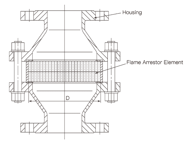
Test 8: Pressure Loss and Vent Capacity Test

1. Test Device

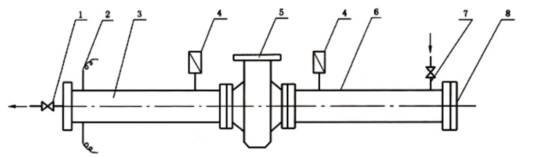
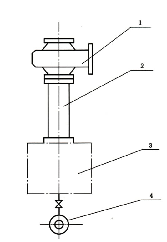
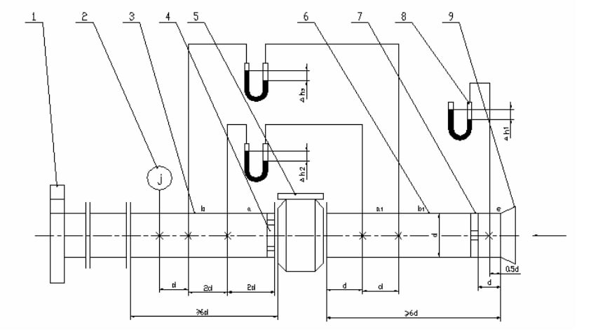
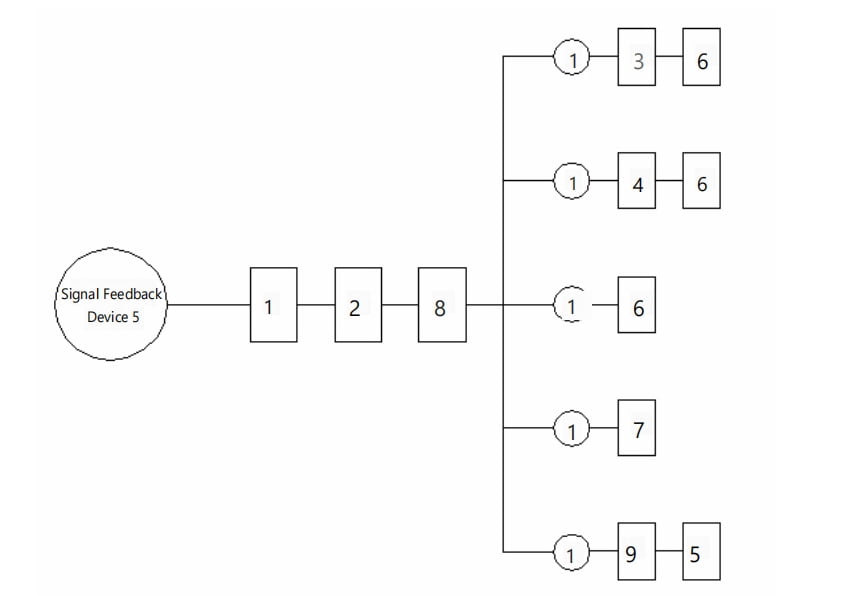
The pressure loss and ventilation capacity test uses a fan to provide the air source, as shown in Figure 3. The inner diameter d of the test pipe should match the nominal diameter of the flame arrester, and the inner wall surface should be smooth and even. All connections in the system must be free from leaks.

Figure 3. Pressure Loss and Vent Capacity Test Device

2. Inlet Specifications:

The inlet end must have no obstructions within a distance of 1.5d from the center of the test pipe (inner diameter ).

3. Pressure Measurement:

Drill four evenly distributed pressure measurement holes with diameters ranging from ø2 mm to ø3 mm around the circumference of the same cross-section of the test pipe, perpendicular to the pipe wall. The surrounding area of these holes should be smooth and free of burrs. Weld short pipes to the outer wall at the static pressure holes for easier connection; the inner diameter of these short pipes should be at least twice the diameter of the measurement holes. Connect each of the four static pressure holes individually to a pressure measurement device. The arithmetic mean of the four static pressure readings will be the average static pressure at that cross-section.

4. Collector Specifications:

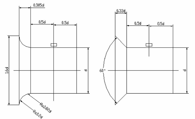
The collector can be either arc-shaped or hammer-shaped, with the dimensions and shape shown in Figure 4. The inner wall surface must be smooth, with a surface roughness value not exceeding 3.2 µm.

Figure 4. The Dimensions of Collector

5. Flow Straighteners:

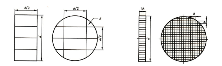
The dimensions of the inlet and outlet flow straighteners are shown in Figure 5. The thickness of the baffles in the flow straighteners should be , and the spacing between the baffles in the outlet flow straightener should be .

Figure 5. Dimensions of Inlet Flow Straighteners and Outlet Flow Straighteners

6. Pressure Measurement Devices:

Use U-shaped manometers with uniform inner diameters, typically 6 mm to 10 mm, and length depending on the pressure being measured.

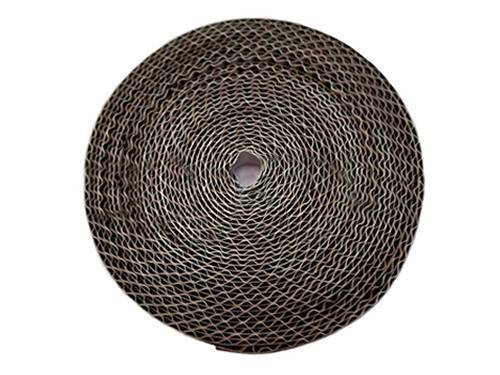
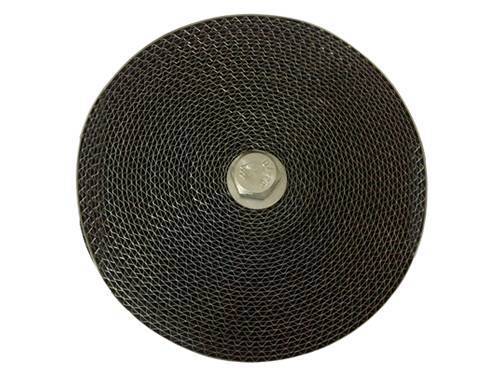
7. Preparation for Testing:

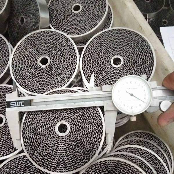
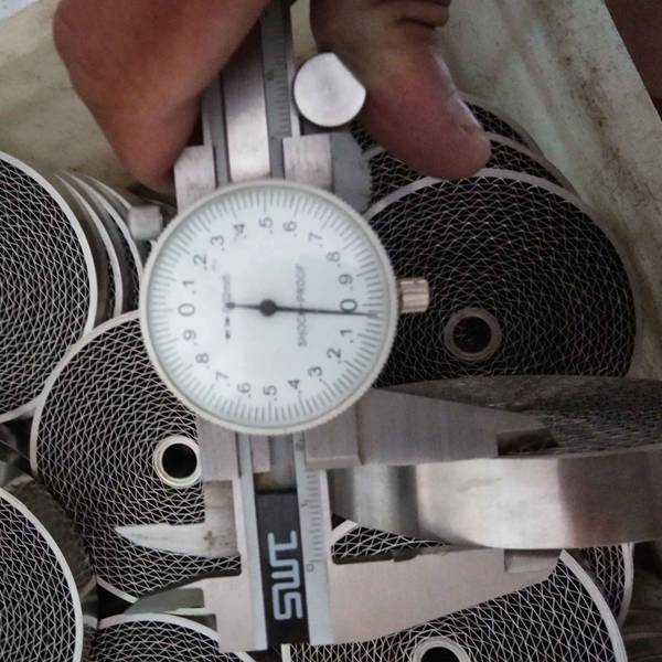
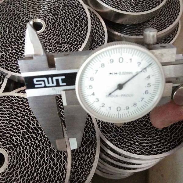
Clean the flame arrester core before installing it in the flame arrester for testing. The test medium should enter from the inlet end of the flame arrester.

8. Test Conditions:

The absolute pressure of the air used as the test medium should be 0.1 MPa, with a temperature of 20°C, a relative humidity of 50%, and a density of 1.2 kg/m³. If the air conditions deviate, convert them to this state.

9. Measurement of Air State:

Measure the air state near the inlet using a pressure gauge, thermometer, and dry-wet bulb thermometer.

10. Conducting the Test:

Start the motor to run the fan, and adjust the valve to regulate the flow rate. Once the liquid level in the manometer stabilizes, record the readings (Δℎ2,Δℎ3) once per minute, three times in total, and take the average value. Calculate the pressure loss using formula (1), and ensure the results meet the requirements of Table 1. Pressure Loss of Flame Arrester.

(Formula 1)

Where:

  • Δh2 is the pressure difference between segments a and a1 in Pascals (Pa);
  • Δh3 is the pressure difference between segments a and a2 in Pascals (Pa).

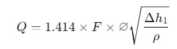
11. Calculating Ventilation Capacity:

Record the stable reading of the manometer at point e () once per minute, three times in total, and take the average value. Calculate the ventilation capacity using formula (2), ensuring the results meet the requirements of Table 2. Vent Capacity of Flame Arrester.

Where:

  • is the collector coefficient (0.98 for conical, 0.99 for arc-shaped);
  • Δh1 is the vacuum at point e in Pascals (Pa);
  • ρ is the density of the ambient air in kilograms per cubic meter (kg/m³).

Flame Arrester Inspection Rules

1 Classification and Inspection Items

1.1 Type Inspection

1.1.1 Type inspection should be conducted under any of the following circumstances:

a) When a new product prototype is undergoing type identification;
b) After official production has commenced, if there are significant changes in product structure, materials, processes, or key manufacturing methods that may affect product performance;
c) In the event of a major quality incident;
d) When production is resumed after a shutdown of more than one year;
e) Upon request by a quality supervision agency.

1.1.2 The items for type inspection should be conducted according to the provisions specified in Table 3.

1.2 Factory Inspection

The items for factory inspection should be conducted according to the provisions specified in Table 3.

1.3 Testing Procedures

The testing procedures should be conducted according to the provisions specified in Appendix A.

2 Sampling Method

Adopt one-time random sampling, with the sample size conforming to the provisions of Appendix A.

3 Determination of Inspection Results

3.1 Type Inspection

  • If all items in the type inspection are qualified, the product is considered qualified.
  • If any Class A item is unqualified, the product is considered unqualified; if two or more Class B items are unqualified, the product is considered unqualified.

3.2 Factory Inspection

  • If all items in the factory inspection are qualified, the product is considered qualified.
  • If any Class A item is unqualified, the product is considered unqualified; if any Class B items are unqualified, double sampling inspection is allowed. If there are still unqualified items, the product is considered unqualified.

Table 3. Inspection Item for Flame Arrester

Name Inspection Items Type Inspection Items Inspection Items Before Shipment Non-Conformance Categories
Full Inspection Sampling Class A Class B
Flame Arrester Appearance
Material
Salt Spray Corrosion Resistance
Sulfur Dioxide Corrosion Resistance
Strength
Explosion Suppression
Burn Resistance
Connection Type
Pressure Loss and Ventilation Capacity

★: Indicates that the item is included in the inspection category.
—: Indicates that the item is not included in the inspection category.

Appendix A

Flame Arrester Test Procedure and Sampling Quantity

The test procedure for flame arresters is conducted according to the provisions specified in Appendix A. Below is a summary of the key steps involved

A 1.1 Test Sequence

  1. Appearance (Test 2)
  2. Material (Test 2)
  3. Salt Spray Corrosion Test (Test 3)
  4. Sulfur Dioxide Corrosion Test (Test 4)
  5. Strength Test (Test 5)
  6. Explosion Suppression Test (Test 6)
  7. Burn Resistance Test (Test 7)
  8. Connection Type (Test 2)
  9. Pressure Loss and Ventilation Capacity (Test 8)

Figure A.1. Flame Arrester Test Procedure

A 1.2 Explanation

a) The test sequence numbers mentioned above are represented by the numbers within the squares in Figure A.1.

b) The numbers within the circles represent the number of samples required for each test.

Flame Arrestor Design Standards

Flame arresters are designed and manufactured according to specific standards and guidelines that ensure they function safely and effectively in preventing flame propagation in systems handling flammable gases or vapors.

ISO/IEC 80079-49:2024 [EN ISO 16852:2016 Withdrawn]

This is a global standard that specifies the requirements and test methods for flame arresters that prevent flame transmission and endure prolonged exposure to flames. It covers flame arresters installed on venting systems or used at other points in systems that could be at risk from deflagration or detonation phenomena. In Explosive Atmospheres part 49, you will find the performance requirements, test methods, and limits for the use of flame arresters.

API 2000

Although primarily a standard for venting atmospheric and low-pressure storage tanks, API 2000 also discusses the importance of flame arresters in preventing fire hazards related to the storage of petroleum and petroleum products.

NFPA 30

The National Fire Protection Association provides guidelines in NFPA 30 for the installation of flame arresters on storage tanks and associated pipelines handling flammable and combustible liquids.

UL Standards

Underwriters Laboratories develops standards and test procedures for flame arresters to ensure they meet safety requirements when used in various applications.

ATEX Directive 2014/34/EU

This European directive covers equipment and protective systems intended for use in potentially explosive atmospheres. Flame arresters used in such environments must comply with ATEX requirements, ensuring they are safe for use in explosive atmospheres

Flame Arrestor Element Design

Composition and Functionality

The flame arrestor element, crafted from alternating layers of corrugated and flat metal strips, serves as the core component of the flame arrestor system. This design effectively halts the propagation of fire by controlling the gap through which flames could potentially pass.

Working Principle

Upon ignition of a gas mixture within a confined gap, the resultant flame moves toward the unburned mixture. The expansion of the combusted gases pre-compresses the adjacent non-combusted mixture, accelerating the flame’s spread. The strategic gap design within the flame arrestor element dissipates heat, transfers the flame to the surface of the corrugated gap, and cools the gases below their ignition temperature, effectively extinguishing the flame.

Applications

This element is particularly crucial in environments involving flammable gas pipelines, including systems that handle gasoline, kerosene, light diesel oil, crude oil, and coal seam gas purification and emission. It is commonly paired with a breather valve to enhance safety in oil storage and gas transport systems.

Parameter Configuration

The effectiveness of a flame arrestor element is dictated by carefully selected parameters, such as the crimp height, thickness, and diameter of the metal strips. These dimensions are critical in tailoring the arrestor to specific safety requirements.

Types of Flame Arrestor Elements

Flame arrestor elements are available in two configurations:

1. Dual Corrugated Strips

Comprising two corrugated metal strips wound together.

2. Corrugated and Flat Strip Combination

Consisting of a corrugated strip and a flat strip alternately wound into a coil, enhancing the turbulence and cooling effect.

Features

  • Explosion-Proof: Designed to withstand severe explosive forces.
  • Corrosion Prevention: Materials selected to resist corrosive environments.
  • Fire Resistance: High resistance to catching fire.
  • Ease of Maintenance: Simple to clean and maintain.
  • Installation Simplicity: Designed for easy and quick installation.
  • Variety in Specifications: Available in multiple specifications to suit diverse applications.
  • Textural Options: Offered in different materials to match specific requirements.

Classical Applications

  • General Flame Arrestors: For broad applications in various systems.
  • Atmospheric Tanks: Protects storage systems exposed to atmospheric conditions.
  • Oil Storage Tanks: Safeguards reservoirs of flammable liquids.
  • Gas Pipelines: Ensures safe transport of gases without the risk of ignition.

Flame Arrester Diagram

Flame arrestor element

Flame Arrestor Element Material

Flame arrestors element are typically constructed from stainless steel due to its high melting point, excellent thermal conductivity, corrosion resistance, and structural stability under high temperatures. Stainless steel ensures that the flame arrestor can withstand intense conditions without deforming. In contrast, materials such as aluminum or copper, though lightweight, are prone to deformation and even failure under strong flashback pressures, compromising their effectiveness in arresting flames.

Flame Arrestor Element Specifications

D (Diameter)

Represents the maximum diameter of the flame arrestor element. It is crucial that the total void area of the flame arrestor element is at least equal to or greater than the cross-sectional area of the connecting pipes at both ends to ensure adequate gas flow.

l (Length/Thickness)

Indicates the thickness of the flame arrestor element, essentially the length of the element. This dimension is critical in determining the efficiency of heat exchange between the flame and the arrestor material.

t (Thickness of the Metal Sheet)

The metal sheets used in flame arrestors should be as thin as feasible within processing capabilities and required strength to minimize flow resistance loss. Thinner sheets promote better gas flow while maintaining structural integrity.

h (Height of the Triangle)

Refers to the peak height of a regular triangular unit within the flame arrestor. The design of these triangular units significantly impacts the cooling efficiency and the overall effectiveness of the flame arrestor.

Flame Arrestor Element Design Considerations

The interaction between the flame arrestor element and the flame is pivotal. Greater contact area facilitates more efficient heat exchange, enhancing the fire retardance capability of the arrestor. Optimizing the dimensions of the triangular units and the channels within the arrestor is essential:

  • Smaller triangular units and longer channels increase the cooling efficiency, effectively quenching the flame.
  • Adjusting the height h of the triangular units influences the length l of the channels. A smaller h may reduce the channel length, potentially increasing gas flow resistance, while too short a length l may diminish the flame arrestor’s capability to quench flames.

Flame Arrestor Mesh

Flame arrester element also known as flame arrester mesh.

The mesh in a flame arrester plays a critical role in stopping the propagation of flames in systems handling flammable gases or vapors. This mesh component is designed to absorb and dissipate the heat from a flame, cooling it below its ignition temperature and thereby preventing it from traveling further down the pipeline or vent system.

Key Characteristics of Flame Arrester Mesh

Performance Considerations of Flame Arrester Mesh

Pressure Drop

The mesh design must balance flame suppression with minimal resistance to flow, to avoid significant pressure drops across the arrester.

Clogging Risk

Fine mesh designs can trap particles and residues, which might lead to clogging, reducing gas flow and requiring regular maintenance.

Thermal and Mechanical Stability

The mesh must maintain its integrity under the thermal stresses of a flame and the mechanical stresses of system operations.

Flame Arrester Installation Guide

Installation by Position

The location significantly impacts the choice of flame arrestor due to varying distances between the ignition source and the arrestor, which influences flame propagation speeds.

For example, flame arrestors designed for storage tanks are suitable only for short ventilation pipes. They can function independently or in conjunction with a breather valve. The distance between the arrestor and the potential flashback point should not exceed five times the diameter of the connecting pipe. These arrestors are only effective in environments containing flammable gases without open flames and can arrest flames with propagation speeds of no more than 45 m/s, making them unsuitable for replacing pipeline flame arrestors.

Installation by Function

  • Combustible Gas Pipelines: In scenarios where a gas delivery pipeline connects directly to a burner without other backfire prevention mechanisms, it is mandatory to install a flame arrestor.
  • Deflagration Flame Arrestors: Ideal for arresting flames propagating at subsonic speeds, these should be positioned close to the ignition source.
  • Detonation Flame Arrestors: Designed to handle flames traveling at supersonic or near-sonic speeds, these should be installed at greater distances from the ignition source. The table below outlines the minimum required installation distances based on the nominal diameter of the pipe:
Pipe Nominal Diameter (DN) 15 20 25 32 40 50 65 80 100 125 150 200
Min. Installation Distance (m) 0.5 1 1.5 2 3 4 6 8 10 10 10 10

Additional Considerations:

  • Environmental Adaptations: In cold climates, select flame arrestors with heating jackets or utilize alternative heating methods to prevent freezing.
  • Special Features: Depending on the specific application, flame arrestors equipped with flushing pipes, pressure gauges, thermometers, and drain outlets can be selected.
  • Connection Types: Use threaded connections for flame arrestors at pipeline ends if the nominal diameter is less than DN50. For diameters equal to or greater than DN50, flange connections are recommended.
  • Protective Covers: Install rainproof and ventilated covers that open automatically on arrestors at the end of pipelines.
  • Branch Installations: Choose detonation flame arrestors for all branch connections between storage tanks.
  • Top of Storage Tank Installations: For oil and gas discharge pipes at the top of storage tanks, select and install detonation flame arrestors at the connection points with the tank. Additionally, install an emergency emptying pipe for protective gas and oil and gas discharge lines.

These guidelines ensure that flame arrestors are selected and installed correctly to provide optimal safety and performance based on their intended function and environmental conditions.

FAQs| Flame Arrester

Why Flame Arrester Required

Flame arresters are essential safety devices for the protection of storage tanks, vessels, and process equipment that handle flammable gases or vapors. They are particularly crucial in situations where there is a potential for fire or explosion. Here are the main reasons why flame arrestors are required.

a. Enhanced Safety for Venting Systems

  • Vents are pivotal for the safe operation of storage tanks and vessels, providing necessary ventilation to accommodate both normal and emergency scenarios. Following the guidelines of API 2000/ISO 28300, vents facilitate the independent ventilation of vessels, thus ensuring safety under various operational conditions. Flame arresters are integrated into these systems to prevent flames from entering a vessel through the venting system, which could cause a catastrophic explosion or fire.

b. Performance and Efficiency

  • YeeValve vents are designed with weight-loaded valve discs that achieve full valve lift once pressures exceed 10% above the set pressure. This design allows for rapid pressure relief, maximizing performance while minimizing product losses. Incorporating flame arresters into these systems enhances this efficiency by ensuring safety without compromising the venting function.

c. Durability and Reliability

  • Constructed with corrosion-resistant materials such as standard valve seats, discs, and spindles, these vents are built to last. They also feature high-quality sealing technologies, including a metal foil and an air cushion, to minimize leak rates. This durability is particularly beneficial in explosive atmospheres where the integrity of the venting system is critical. The addition of flame arresters further ensures that these systems can reliably prevent the ignition of flammable mixtures, even under high set pressures.

d. Certified Safety

  • The vents, particularly those equipped with flame arrester elements, undergo strict testing and certification to ensure they meet safety standards. As per the EC Directive 94/9/EC, these systems are not only tested for their ability to handle inflammable mixtures but are also certified as safety systems. This means they are recognized for their capability to stop flame propagation, thereby safeguarding the equipment and personnel from potential hazards.

e. Integrated Safety Solutions

  • Integrating a flame arrester with the vent combines the benefits of both systems into a single, compact device. This integration not only simplifies the overall system design but also enhances the safety features by ensuring that any flames or sparks that could result from the venting of flammable gases are effectively contained and extinguished.

Where are Flame Arrestors Required

Flame arresters are vital safety devices used in various industries to prevent the propagation of flames and ensure safe operations. Their primary function is to stop flames from spreading through flammable gas or vapor mixtures, thereby mitigating the risk of explosions and fires. Here are some key areas where flame arresters are commonly used.

1. Storage Tanks – Diesel and Fuel Storage Tanks:

  • Flame arresters are installed on vents of diesel and other fuel storage tanks to prevent external ignition sources from igniting the flammable vapors inside the tank.
  • They are also used to prevent flames from propagating into the tank in case of an internal ignition.

2. Chemical Processing Plants – Reactor Vents and Relief Systems:

  • Used to protect chemical reactors and relief systems by preventing external flames from igniting the volatile gases within the system.
  • Ensure safe venting of gases during emergency relief scenarios.

3. Oil and Gas Industry

  • Pipeline Protection:
    • Installed on pipelines transporting flammable gases or liquids to prevent the spread of flames along the pipeline.
    • Essential for offshore platforms and refineries where the risk of gas leaks and explosions is high.
  • Storage and Transportation:
    • Flame arresters are used in storage tanks, tanker trucks, and railcars to prevent explosions during the storage and transportation of flammable liquids and gases.

4. Pharmaceutical Industry – Solvent Recovery Systems:

  • Used in systems that recover flammable solvents to prevent the spread of flames through the piping and equipment.
  • Protects the equipment and environment from potential fire hazards.

5. Waste Treatment Facilities

  • Biogas Plants:
    • Installed on biogas digesters and storage tanks to prevent flames from entering the system, ensuring the safe handling of biogas.
    • Used to protect the entire biogas processing and storage infrastructure.
  • Landfill Gas Systems:
    • Used in landfill gas extraction systems to prevent flames from traveling back into the landfill, which could cause fires or explosions.

6. Marine Applications – Marine Fuel Tanks:

  • Installed on the vents of marine fuel tanks to prevent the ignition of flammable vapors, ensuring the safety of ships and offshore platforms.
  • Essential for complying with marine safety regulations.

7. Power Generation – Generator Fuel Systems:

  • Used in the fuel supply systems of power generators to prevent the ignition of flammable vapors and ensure continuous safe operation.
  • Protects both the generator equipment and surrounding infrastructure.

8. Industrial Manufacturing – Paint and Coating Facilities:

  • Used in facilities where flammable solvents and coatings are used to prevent fires and explosions.
  • Essential for spray booths and drying ovens where solvent vapors can accumulate.