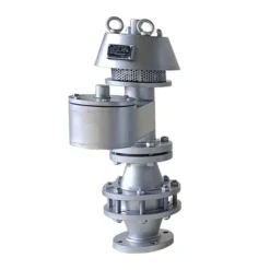
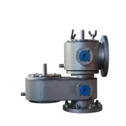
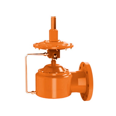
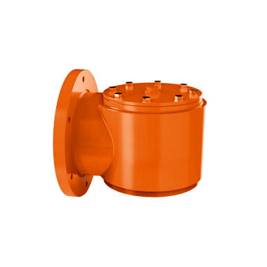
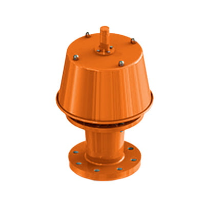
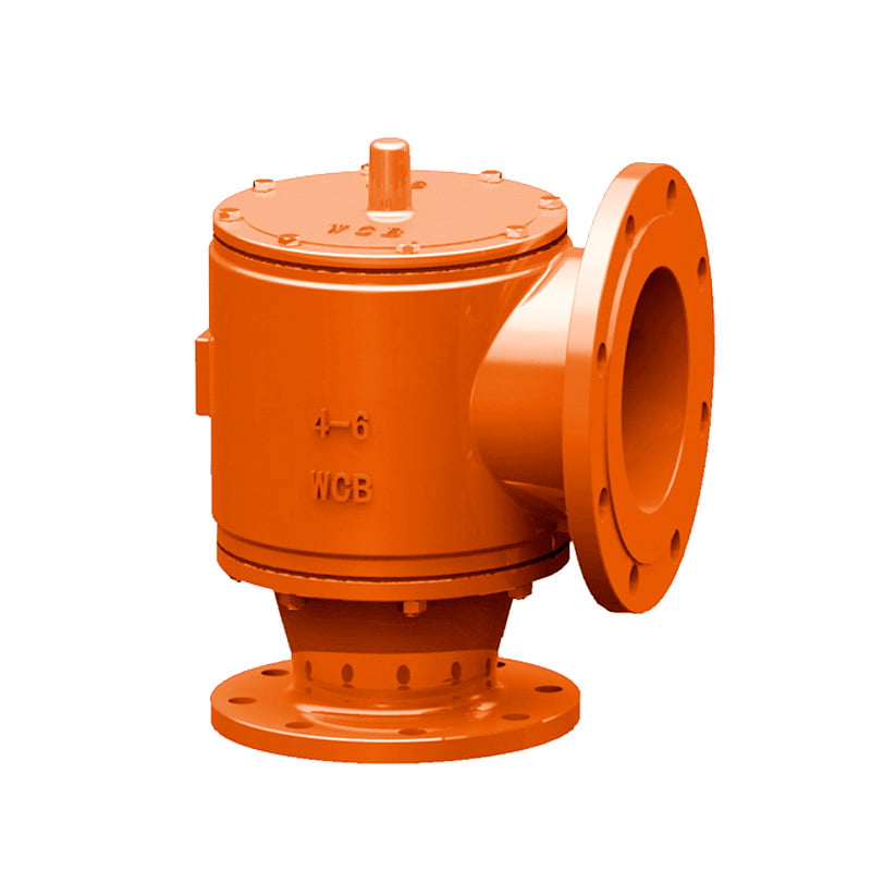
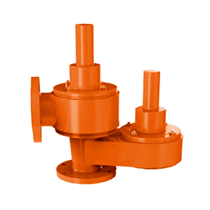
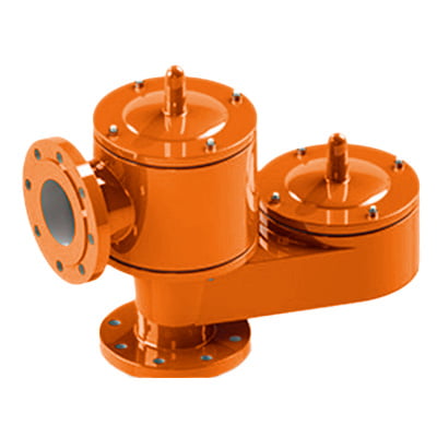
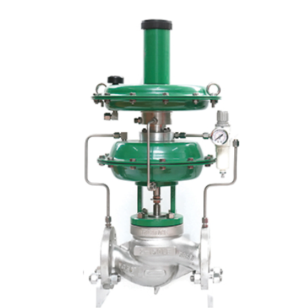
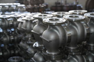
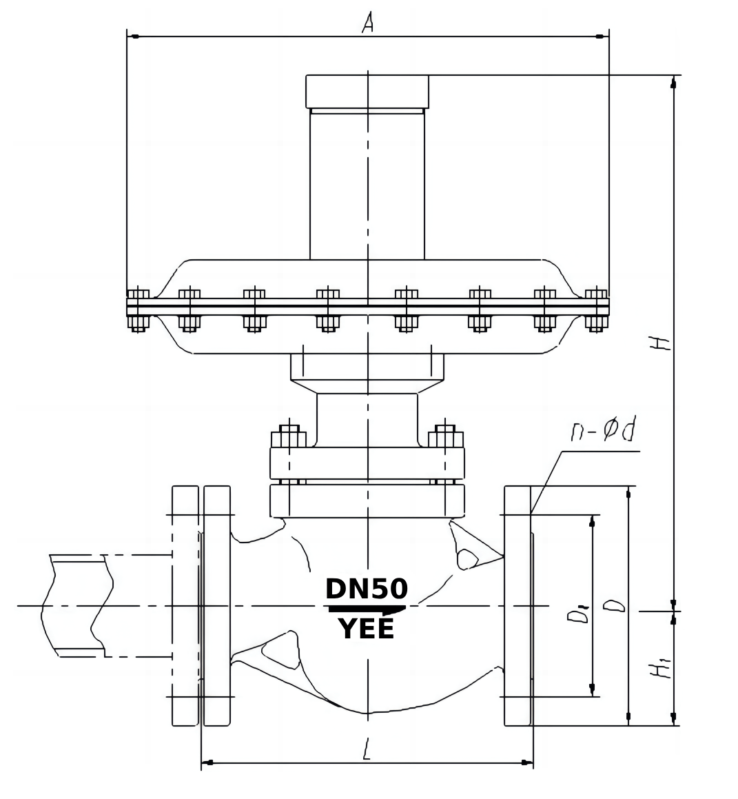
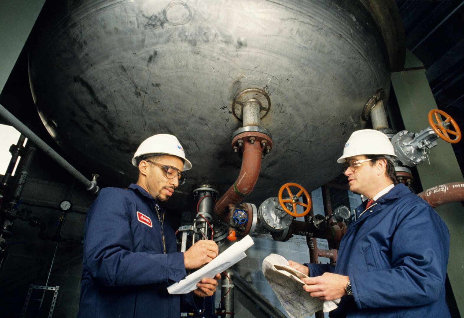
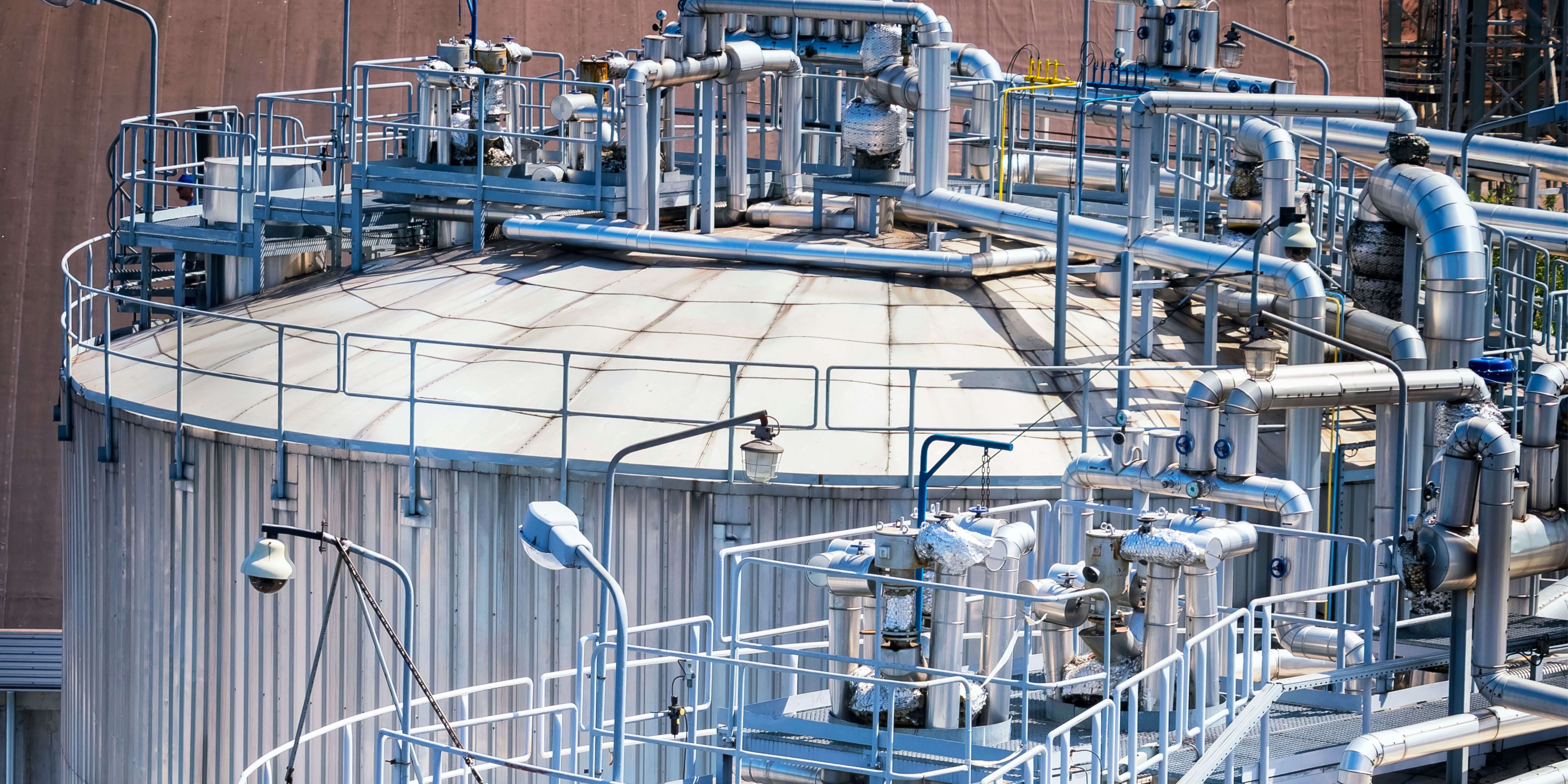
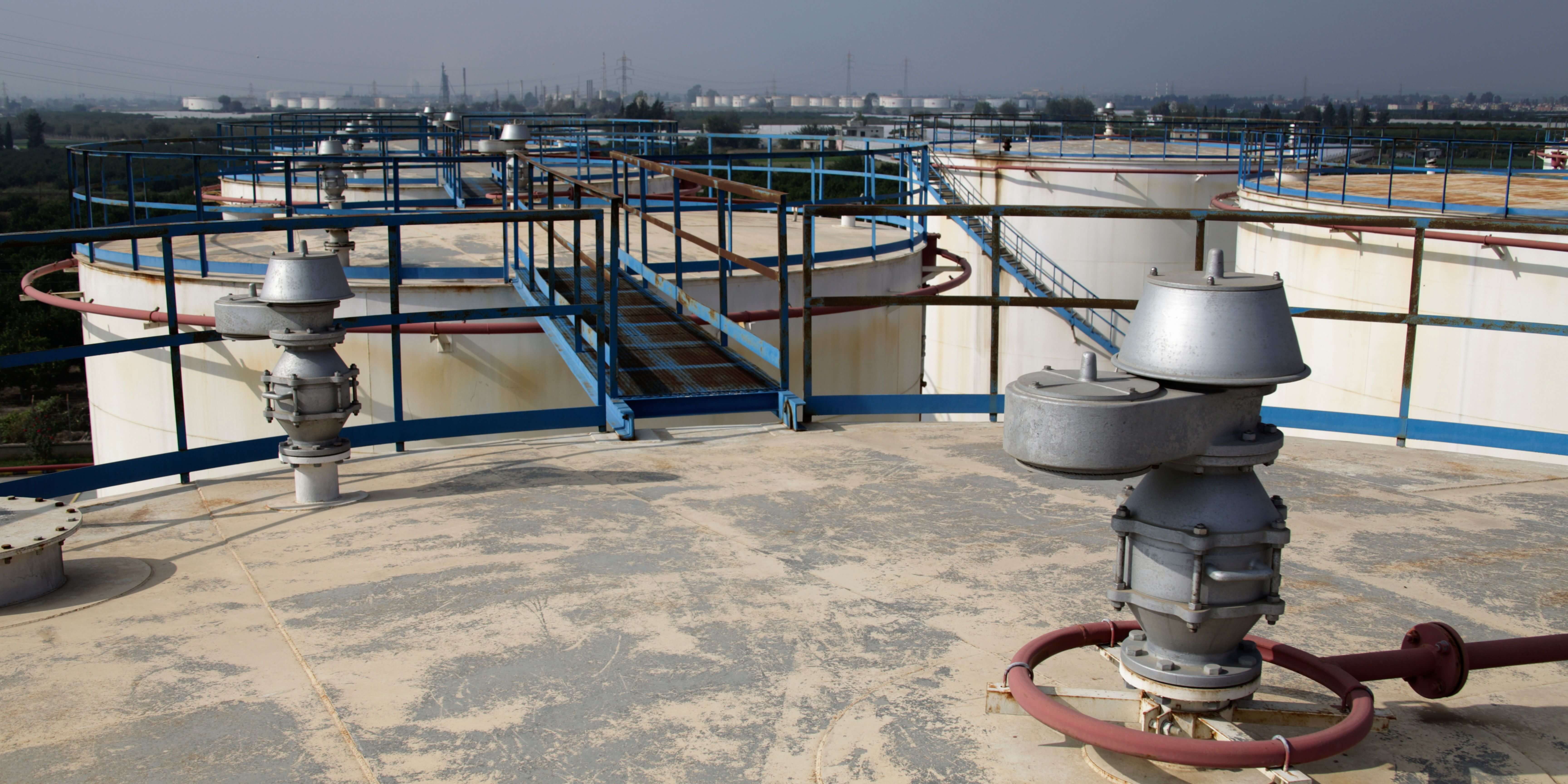
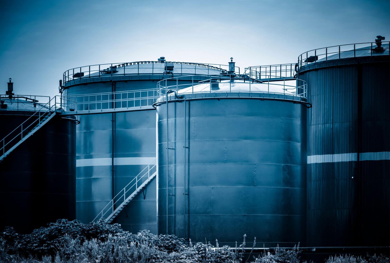
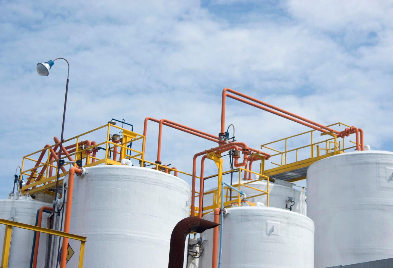
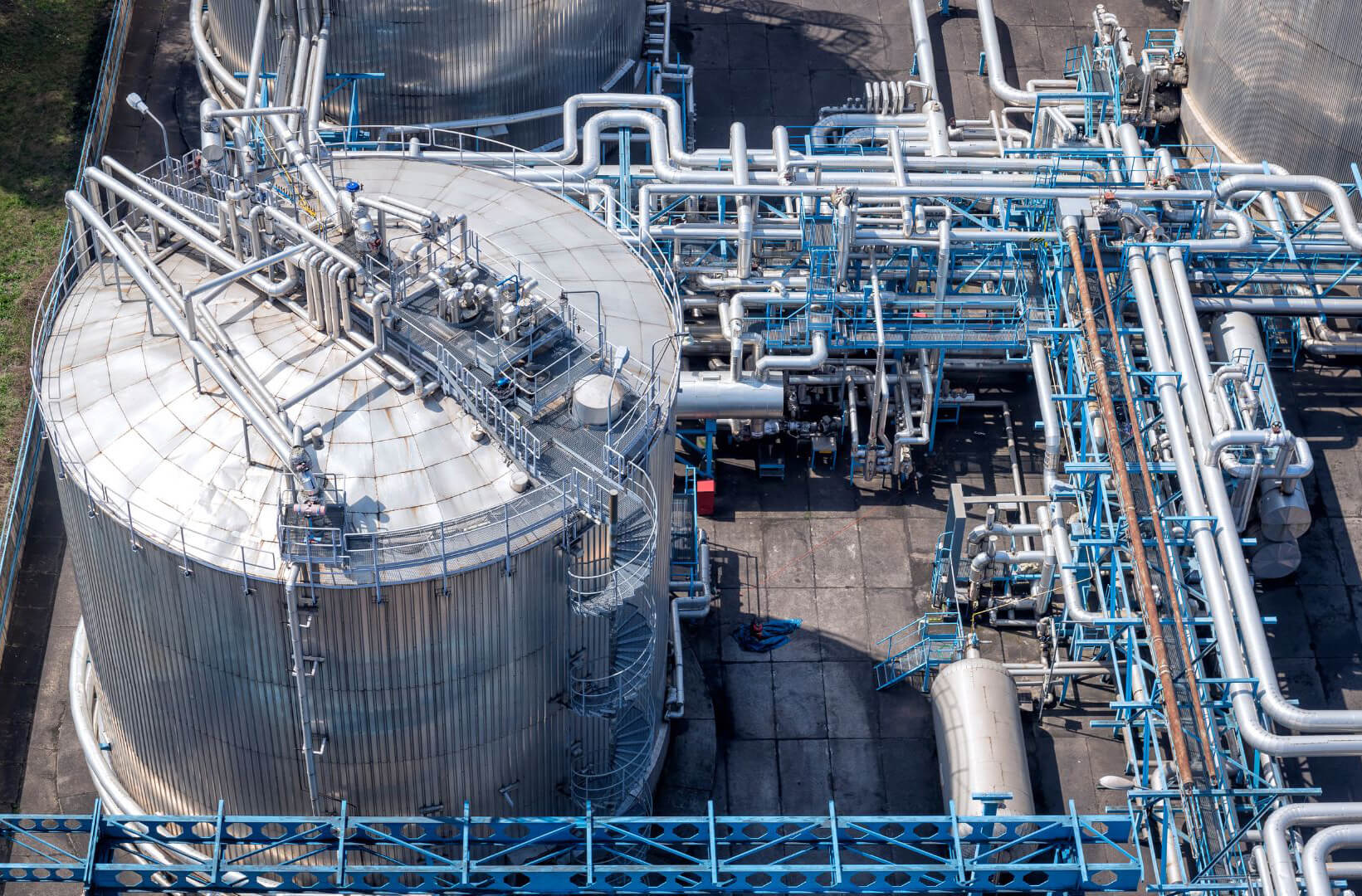
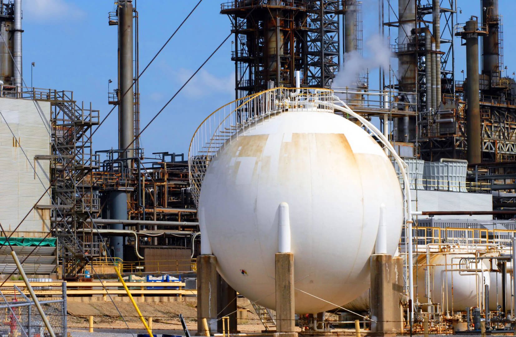
Reliable N2 Blanketing Valve Manufacturer 

At YeeValve, we specialize in manufacturing high-quality N2 blanketing valves, designed to ensure the safety and integrity of storage tanks. Our valves are engineered to maintain a consistent nitrogen atmosphere, preventing contamination and minimizing the risk of oxidation and combustion.

View Products Request A Quote

WHAT IS N2 BLANKETING VALVE

The N2 blanketing valve is designed to maintain constant gas pressure in the vapor space of storage tanks. Itis capable of regulating the desired pressure within specific limits when liquid runs out or when a vacuum occurs due to a temperature decrease. Additionally, it serves to prevent air and humidity from entering the storage vessel, thereby preserving products and safeguarding against fire. The controller also plays a critical role in protecting the tank from explosions by restricting sparks and preventing fluid outflow through evaporation.

  • Size: DN20~DN300
  • Pressure Rating: PN1.6~PN6.4MPa, Class 150~300LB
  • Fange Standard: JB/T79.1-94.79.2-94, ANSI B16.
  • Body Material: Cast iron, Cast steel, Stainless Steel
  • Plug Type: Single-seated, Double-seat, Cage guided
  • Stem Material: Stainless Steel
  • Pressure Balance: Stainless steel bellows
  • Flow Characteristic: Quick open
  • Working Temperatures: 80℃

Adjusting Setting Pressure Range

Nominal Diameter DN(mm) 20 25 32 40 50 65 80 100 125 150 200 250 300
Rated Flow Characteristic Kv Single-Seated 7 11 20 30 48 75 120 190 300 480 760
Cage Type 7 11 20 30 48 75 120 190 300 480 760
Double-Seated 22 33 53 83 132 209 330 528 836 1210 1925
Rated Travel (mm) 8 10 14 20 25 40 50 60 70
Adjusting Pressure Range (kPa) 15~50,40~80,60~100,80~140,120~180,160~220,200~260,240~300,280~350,330~400,380~450,
430~500

Main Parameters for Micro Flow Single-Seat Natural Gas Regulator

Nominal Diameter
DN(mm)
20, 25
Seat Diameter(mm) 6 7 8 10 12 15
Rated Flow
Characteristic Kv
0.01 0.02 0.048 0.06 0.08 0.12 0.2 0.32 0.5 0.8 1.8 2.8 4.4
Rated Travel (mm) 5

N2 Blanketing Valve Carbon Steel

Body Material WCB, WCC, WC6, WC9, LCB
Trim Material 304/316 304/316 304/316 304/316
Treatment RTFE   ST SS
Seat Material 304/316 304/316 304/316 304/316
Treatment RTFE ST SS
Allowed Leakage Class Ⅳ/Ⅴ/Ⅵ Ⅳ/Ⅴ Ⅳ/Ⅴ
Standard GB/T4213,FCI70.2
Service Temperature
(℃)
WCB, WCC -5~+160 -5~+230 -5~+425 -5~+425
WC6, WC9 -5~+160 -5~+230 -5~+538 -5~+538
LCB -45~+160 -45~+230 -45~+350 -45~+350

N2 Blanketing Valve Stainless Steel

Body Material CF3, CF8, CF3M, CF8M
Trim Material 304/316 304/316 304/316 304/316
Treatment RTFE ST SS
Seat Material 304/316 304/316 304/316 304/316
Treatment RTFE ST SS
Allowed Leakage Class Ⅳ/Ⅴ/Ⅵ Ⅳ/Ⅴ Ⅳ/Ⅴ
Standard GB/T4213, FCI70.2
Service Temperature(℃) -45~+160 -196~538 -196~538 -196~538

Working Principle of N2 Blanketing System

The N2 blanketing system consists of an N2 supply device and an N2 relief device. The N2 supply device includes a controller and a main valve, while the N2 relief device typically consists of an internal feedback micro-pressure regulating valve. The N2 blanketing pressure is generally set between 50 to 400 mmH2O and is precisely controlled by the N2 blanketing device.

Filling Tank

When the tank’s inlet valve opens to filling material, the liquid level rises, reducing the gas volume and increasing the pressure. When the internal pressure exceeds the set value of the N2 release unit, the release unit opens to discharge nitrogen, lowering the tank’s pressure. Once the pressure falls below the set point, the release unit closes automatically.

Discharge Tank

When the tank’s outlet valve opens to discharge material, the liquid level drops, increasing the gas volume and lowering the pressure. The N2 supply device then opens to inject nitrogen quickly, raising the tank’s pressure. Once the pressure reaches the set point, the supply device closes automatically.

The breather valve on the top of the tank acts as a safety feature. If the N2 blanketing system fails or cannot meet the flow requirements, the breather valve opens to release excess nitrogen or draw in air, protecting the tank. Under normal conditions, the breather valve remains closed.

Description of Nitrogen Blanketing System

i. The typical nitrogen supply pressure ranges between 0.1 to 1 MPa. The more stable the pressure, the higher the adjustment accuracy of the N2 supply valve, resulting in a more stable N2 blanketing pressure.

ii. The breather valve on the tank top serves only a safety role. It activates when the main valve fails, causing excessive pressure inside the tank. It does not operate under normal conditions.

iii. The N2 release valve is installed on the tank top, usually with the same diameter as the inlet valve.

iv. The pressure set point of the N2 release unit is slightly higher than that of the N2 supply valve. The breather valve’s pressure set point is slightly higher than that of the N2 release unit to prevent frequent operation, which wastes nitrogen and affects equipment lifespan.

v. Provide the chemical composition of the liquid inside the N2-blanketed tank to select the appropriate valve materials.

vi. If the end-user’s conditions differ from the selection manual, contact YeeValve engineers for a customized optimal solution.

Installation Method

Step 1.

Upon receiving the valve on-site, avoid pulling, pressing, or lifting the valve’s pressure guide tube during handling and installation to prevent performance damage. Check for any exterior damage, loose fasteners, and contaminants in the flow path. Verify the product model, position number, and specifications.

Step 2.

Install the pressure take-off point at a suitable distance from the pressure regulating valve, at least six times the pipe diameter, and it should be on the top or side of the pipe to prevent debris from entering the actuator. Install the controller-operated self-operated pressure regulating valve vertically on a horizontal pipe. See the blew diagram for the connection of the pressure take-off joint and the pipe.

Step 3.

Ensure adequate space around the valve for maintenance and operation, and install bypass valves and appropriate pressure gauges upstream and downstream.

Step 4.

Clean the pipeline before installing the pressure regulating valve, as debris can damage the valve’s sealing surface or obstruct the movement of the valve core and actuator, preventing proper operation. Confirm the removal of pipeline dirt, metal shavings, welding slag, and other debris. Check the pipe flanges to ensure a smooth gasket surface. For threaded connections, apply a high-grade sealant to the male threads only, as excess sealant on the female threads can enter the valve body, causing the valve core to stick or dirt to accumulate.

Step 5.

Filter the fluid before use to maximize the performance of the pressure regulating valve.

Step 6.

Close the cut-off valve on the pressure guide tube before use to protect the actuator and the entire valve. Open it during normal operation.

Step 7.

Ensure the direction of the arrow on the valve body matches the installation direction of the pipe.

Step 8.

After installation, perform a leak test on all joints using soapy water or a similar method.

Nitrogen Supply Device (Nitrogen Supply Valve)

Working Principle

  • The nitrogen supply valve does not require an external energy source. It uses the energy of the medium being regulated as the power source.
  • The valve automatically controls the downstream pressure or tank pressure, keeping the tank pressure constant.
  • It is widely used in nitrogen blanketing systems for chemical storage tanks, pharmaceutical storage tanks, ultrapure water tanks, edible oil tanks, and thermal oil tanks, where isolation from air is necessary.

Key Benefits

  • High Precision Control: Ensures precise maintenance of the desired pressure levels within the storage tank.
  • Wide Range of Applications: Suitable for various industries needing nitrogen blanketing to protect against air exposure.
  • Ease of Use: The ability to set and adjust pressure directly on the controller simplifies operation and reduces downtime.
  • Energy Efficiency: Utilizes the inherent energy of the regulated medium, eliminating the need for external power sources.

Features of the Nitrogen Supply Device (Nitrogen Supply Valve)

  • High Control Accuracy: The control accuracy is about twice that of typical direct-operated pressure regulators.
  • Large Adjustment Pressure Ratio: Suitable for controlling micro-pressure gases, with examples like upstream pressure of 0.8 MPa and downstream pressure of 0.0003 MPa.
  • Convenient Pressure Setting: Pressure can be set on the controller, making the process quick, efficient, and time-saving. Settings can be adjusted continuously even during operation.

Applications

  • Chemical Storage Tank Nitrogen Blanketing
  • Pharmaceutical Storage Tank Nitrogen Blanketing
  • Ultrapure Water Tank Nitrogen Blanketing
  • Edible Oil Tank Nitrogen Blanketing
  • Thermal Oil Tank Nitrogen Blanketing

Pressure Regulation Range and Features

  1. Large and Sensitive Detection Diaphragm: Ensures precise control point pressure accuracy.
  2. Separate Signal Detection Actuator and Power Actuator: Allows the pressure reduction ratio of the entire pressure regulator to reach 2000:1.
  3. Adjustable Flow Device: Simplifies debugging and adjustment.
  4. Internal Pressure Compensation Design: Completely eliminates the impact of pressure fluctuations on set point accuracy, resulting in more stable adjustments.
  5. Packing-Free Design: Ensures quick action.
  6. Segmented Pressure Set Point Range: Overlapping ranges facilitate easy selection.
  7. Convenient Pressure Setting: Allows continuous, interference-free adjustment during operation, maintenance-free.
  8. Detailed Pressure Set Point Range: Refer to the specifications and technical parameters table. It is recommended to select the commonly used pressure set value near the middle of the range.
  9. Minimum Inlet Pressure Requirement: The nitrogen supply valve requires a certain driving pressure. The upstream pressure must not be lower than 200 KPa (gauge pressure).
Size DN 15 20 25 32 40 50 65 80 100 125 150 200
L 130 150 160 180 200 230 290 310 350 400 480 600
H 690 690 690 705 705 760 800 800 840 880 980 1050
A φ308, φ394
L1 233 233 233 332 332 373 572 572 673 980 980 1200
P≥ 135 135 170 220 220 235 245 325 425 550 660 900
H1 330
GW(kg) 18 18 18 25 27 42 65 80 108 182 260 305

Operating Procedures For N2 Supply System

Initial Startup and Post-Maintenance Startup

  • Before operation, check that the design pressure, temperature, and flow rate before the valve match actual working conditions. 
  • After confirming the controller-operated self-operated pressure regulating valve’s main valve core is in the initial position, close the bypass manual valve (if any), open the downstream manual cut-off valve, then open the downstream pressure guide tube cut-off valve, and finally, slowly open the upstream manual cut-off valve.

control valve body

Normal Operation

  • The product is adjusted according to user requirements at the factory and is ready for use upon arrival. However, if process parameters change, the downstream pressure may not reach the specified value. Manually adjust the set pressure by adjusting the thin nut in the controller to raise or lower the downstream pressure to the specified value. If necessary, use the air filter regulator and throttle valve to adjust the downstream pressure to the specified value, ensuring the air filter regulator pressure gauge reads below 0.35 MPa. Observe the downstream pressure gauge until the downstream pressure meets the requirements, then put it into normal operation. 2.2.
  • During normal operation, monitor the upstream pressure gauge for stability and the downstream pressure gauge for compliance with requirements. For a normal shutdown, first close the upstream manual cut-off valve, then the downstream pressure guide tube cut-off valve, and finally the downstream manual cut-off valve. For a fault shutdown, first close the upstream manual cut-off valve, then the downstream pressure guide tube cut-off valve, and the downstream manual cut-off valve, and finally open the bypass valve (if any).
Size DN 15 20 25 32 40 50 65 80 100 125 150 200
L 130 150 160 180 200 230 290 310 350 400 480 600
A φ280, φ308, φ394, φ498
H₁ 42 42 48 56 64 76 85 100 110 126 160 202
H 450 450 450 470 485 490 530 550 560 650 660 900
GW(KG) 12 12 13 14 16 19 28 45 78 130 200 265

Problems & Solve Solution For  N2 Supply Device

NO. Problem Possible Cause Corrective Action Steps
1 Downstream pressure does not drop, remains above the set value 1. Diaphragm of the controller is damaged
2. Spring stiffness of the controller is too high
3. Throttle valve opening is too small
1. Replace the diaphragm: Inspect the controller diaphragm for damage and replace it if necessary.
2. Replace the spring: Check the spring in the controller. If the spring stiffness is too high, replace it with a spring of appropriate stiffness.
3. Adjust the throttle valve opening: Ensure that the throttle valve is adequately opened. Adjust the opening as required to allow for proper pressure regulation.
2 Downstream pressure does not rise, remains below the set value 1. Spring stiffness of the controller is too low
2. Throttle valve opening is too large
3. Main diaphragm is damaged
1. Replace the spring: Inspect the spring in the controller. If the spring stiffness is too low, replace it with a spring of appropriate stiffness.
2. Adjust the throttle valve opening: Ensure that the throttle valve is not excessively open. Adjust the opening to allow for proper pressure regulation.
3. Replace the diaphragm: Inspect the main diaphragm for damage and replace it if necessary.
3 Large leakage when valve is fully closed 1. Valve stem or push rod is stuck
2. Foreign matter or wear on valve core
3. Valve seat threads are corroded
1. Check alignment and reinstall: Inspect the valve stem and push rod for proper alignment. If they are stuck, realign and reinstall them correctly.
2. Remove foreign matter or replace valve core: Check for any foreign matter on the valve core or signs of wear. Clean any debris or replace the valve core if it is worn out.
3. Replace valve seat: Inspect the valve seat threads for corrosion. If corroded, replace the valve seat.
4 Pressure is applied to the diaphragm chamber, but no action occurs 1. Controller malfunction
2. Valve stem is bent or broken
3. Pipeline blockage
1. Inspect the controller: Check the controller for any malfunctions. Repair or replace the controller if it is faulty.
2. Replace the valve stem: Inspect the valve stem for bends or breaks. Replace the valve stem if it is damaged.
3. Clean the pipeline: Check the pipeline for any blockages. Clean the pipeline thoroughly to ensure there is no obstruction.
Notes:
  • Regular inspection and maintenance of the components are essential to ensure the system operates correctly.
  • Follow safety procedures when handling and inspecting components.
  • If the issue persists, consult with YeeValve engineers for further assistance or custom solutions.

Operating Procedures For Nitrogen Relief System

Initial Startup and Post-Maintenance Startup

a. Before operation, ensure the design pressure, temperature, and flow rate upstream of the valve match actual working conditions.

b. During initial startup and post-maintenance startup, confirm that the valve core of the self-operated micro-pressure regulating valve is in the initial fully closed position. If there is a bypass, first close the bypass manual valve, then open the downstream manual cut-off valve, and finally, slowly open the upstream manual cut-off valve.

Normal Operation

a. The product is adjusted according to user requirements at the factory and is ready for use upon arrival. However, if process parameters change and the upstream pressure does not meet usage requirements, manually adjust the set point to change the upstream pressure. Adjust the nut to change the spring preload and modify the upstream pressure set value. Monitor the upstream pressure gauge until the upstream pressure meets the requirements, then put it into normal operation.

b. During normal operation, only observe the upstream pressure gauge to ensure the pressure is stable and meets the requirements.

  • Normal Shutdown: First, close the upstream manual cut-off valve, and finally close the downstream manual cut-off valve.
  • Fault Shutdown: First, close the upstream manual cut-off valve, then close the downstream manual cut-off valve, and finally open the bypass valve.

Problems & Solve Solution For N2 Relief Device

NO. Problem Possible Cause Corrective Action Steps
1 Upstream pressure does not rise, remains below the set value 1. Spring stiffness is too low
2. Valve core is blocked by foreign matter
3. Valve stem is stuck
4. Valve core or seat is damaged, causing excessive leakage
5. Valve port diameter is too large
1. Replace the spring: Inspect the spring in the controller. If the spring stiffness is too low, replace it with a spring of appropriate stiffness.
2. Reassemble: Disassemble the valve, check for blockages or foreign matter, clean if necessary, and reassemble.
3. Readjust: Check the valve stem for proper alignment and operation. If it is stuck, adjust or realign it as needed.
4. Regrind or replace: Inspect the valve core and seat for damage. If they are damaged and causing leakage, regrind or replace them.
5. Replace with a smaller diameter valve: If the valve port diameter is too large, replace it with a valve that has a smaller port diameter to ensure proper pressure control.
2 Upstream pressure does not drop, remains above the set value 1. Spring stiffness is too high
2. Valve port diameter is too small
3. Valve core, stem, or push rod is stuck
1. Replace the spring: Inspect the spring in the controller. If the spring stiffness is too high, replace it with a spring of appropriate stiffness.
2. Replace with a larger diameter valve: If the valve port diameter is too small, replace it with a valve that has a larger port diameter to ensure proper pressure control.
3. Eliminate cause of blockage, readjust: Inspect the valve core, stem, and push rod for any blockages or sticking. Remove any foreign matter, ensure all components move freely, and readjust as necessary.
3 Upstream pressure fluctuates too frequently 1. Valve port diameter is too large
2. Actuator chamber capacity is too small
1. Select an appropriate valve port diameter: If the valve port diameter is too large, replace the valve with one that has a more suitable port diameter to ensure stable pressure control.
2. Add a damper to the pressure guide tube: Install a damper in the pressure guide tube to increase the damping effect and stabilize the pressure fluctuations.

Why Buy Breather Valves from YeeValve?

Features and Benefits of Purchasing Breather Valves from YeeValve

1. High Flow Capacity

Our Pressure/Vacuum Relief Valves offer high flow rates from a compact design, maximizing efficiency.

2. Versatile Settings

A broad range of pressure and vacuum settings ensures optimal tank protection while minimizing gas losses.

3. Industry Compliance

YeeValve’s breather valves are designed and manufactured to meet API Standard 2000:2014 and EN ISO 28300:2016, which ensures high-quality and reliability for the end-users.

4. Enhanced Sealing

Our valves with superior sealing technology meet the strict requirements of emission control regulations.

5. Exceptional Leakage Control

YeeValve exceed the seat leakage standards set by API Std 2000:2014 and EN ISO 28300:2016, with no measurable leakage below 90% of set pressures and less than 1 SCFH (0.03 m3/h) at 90% of the set pressure.

6. Reduced Evaporation Loss

Our breather valve with Low leakage rates significantly cut down on evaporation losses, preserving more of your product.

7. Cost Savings

With economic benefits arise from minimized product loss from YeeValve breather valves, which enhances overall operational efficiency.

8. Customization Options

We do not only produce standard valves but also provide custom services, such as different connection requests from engineering companies to meet their specific installation needs.

9. Valve Sizing Service

We provide a valve sizing service to ensure optimum valve performance and a cost-effective technical specification to meet our customers’ unique needs.

10. YeeValve Technical Support

YeeValve offers professional technical support to assist with any inquiries or issues, ensuring smooth operation and maintenance.