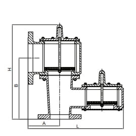
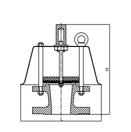
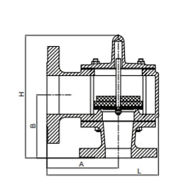
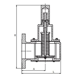
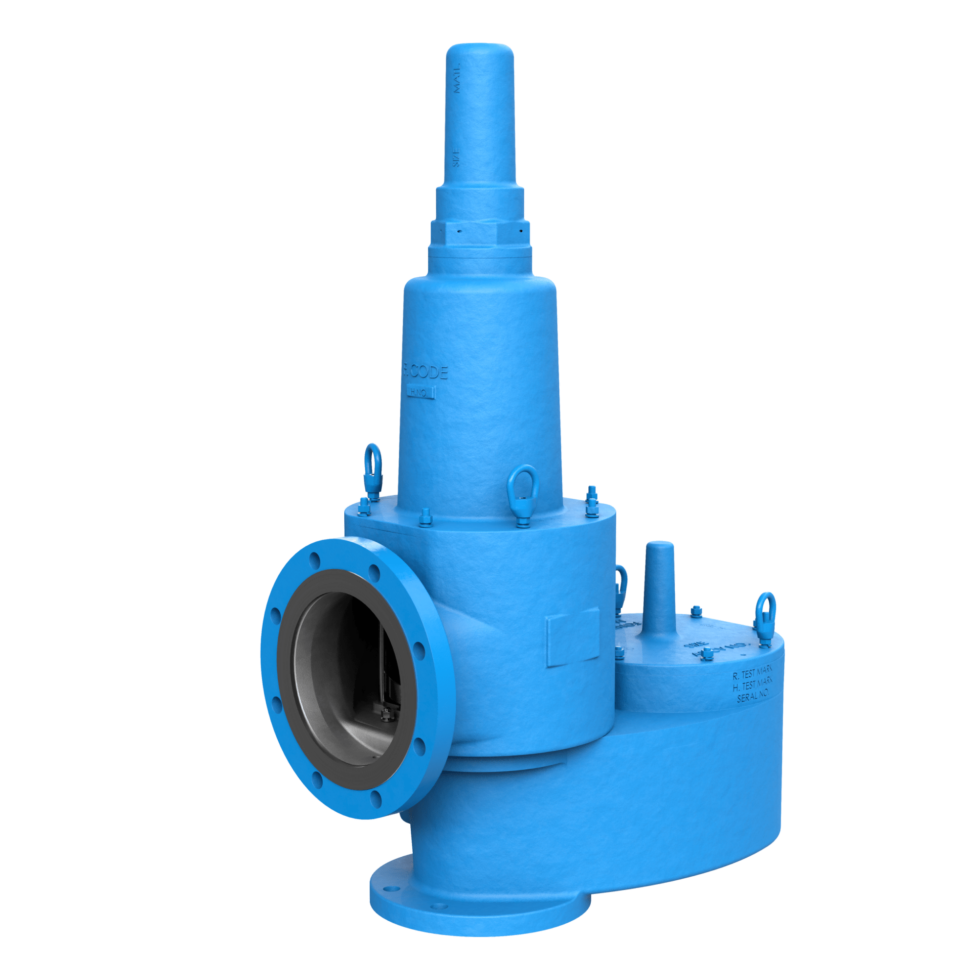
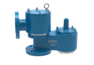
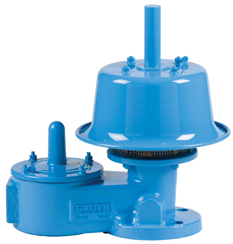
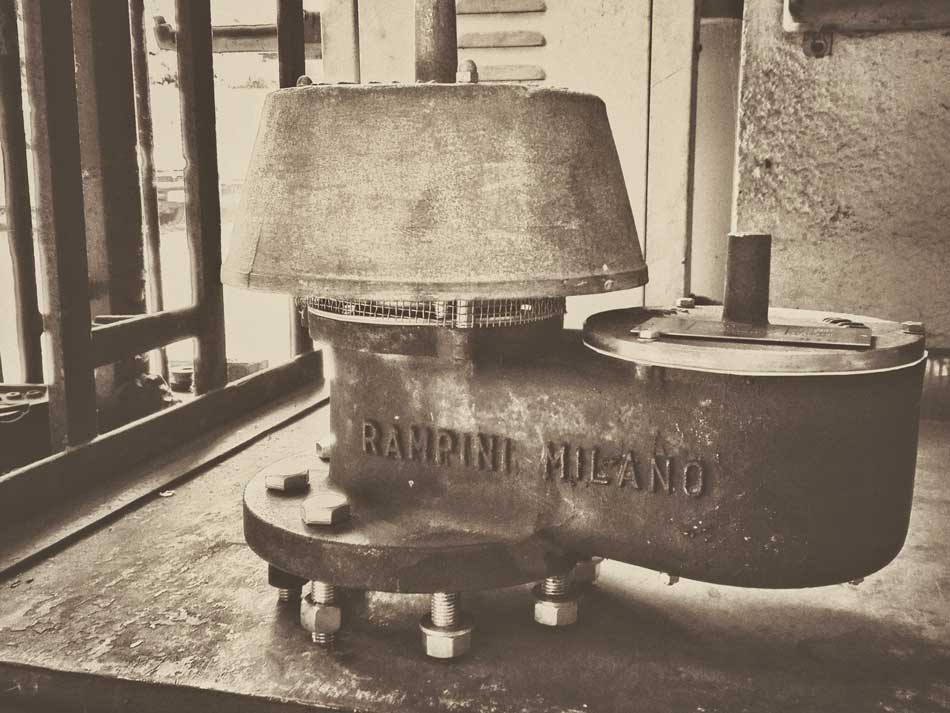
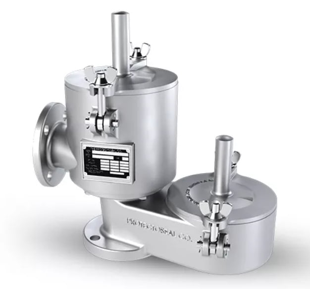
Your Trusted China Top Breather Valve Manufacturer 

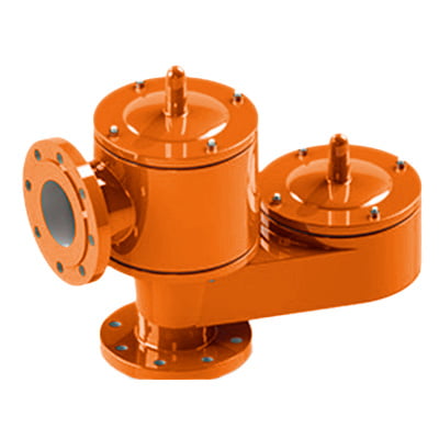
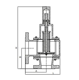
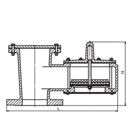
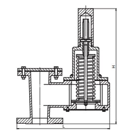
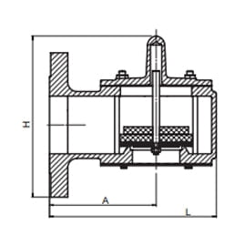
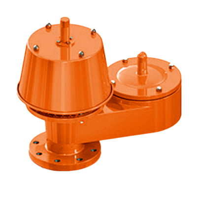
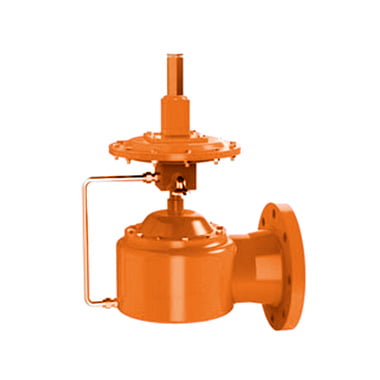
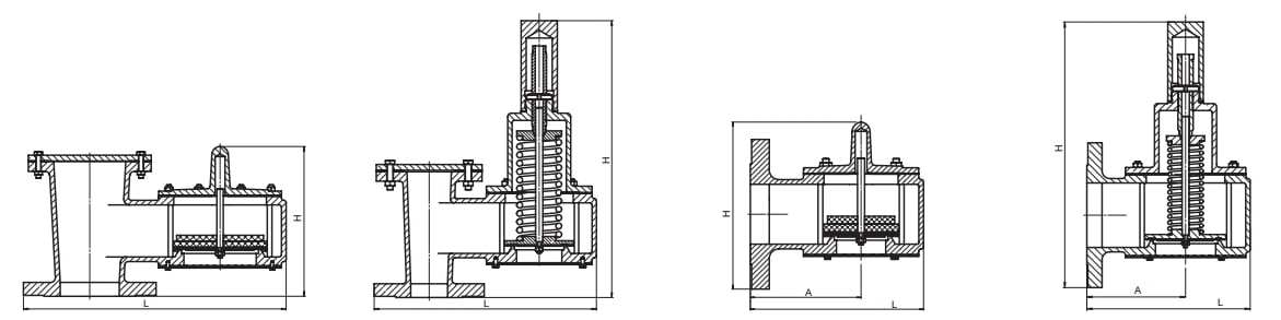
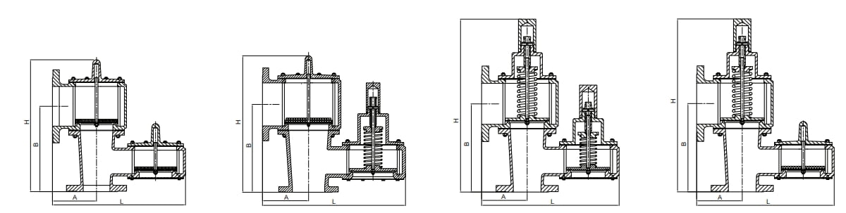
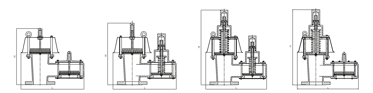
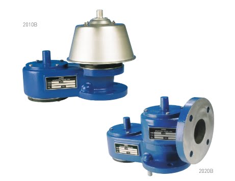
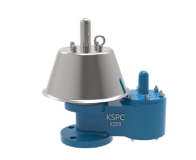
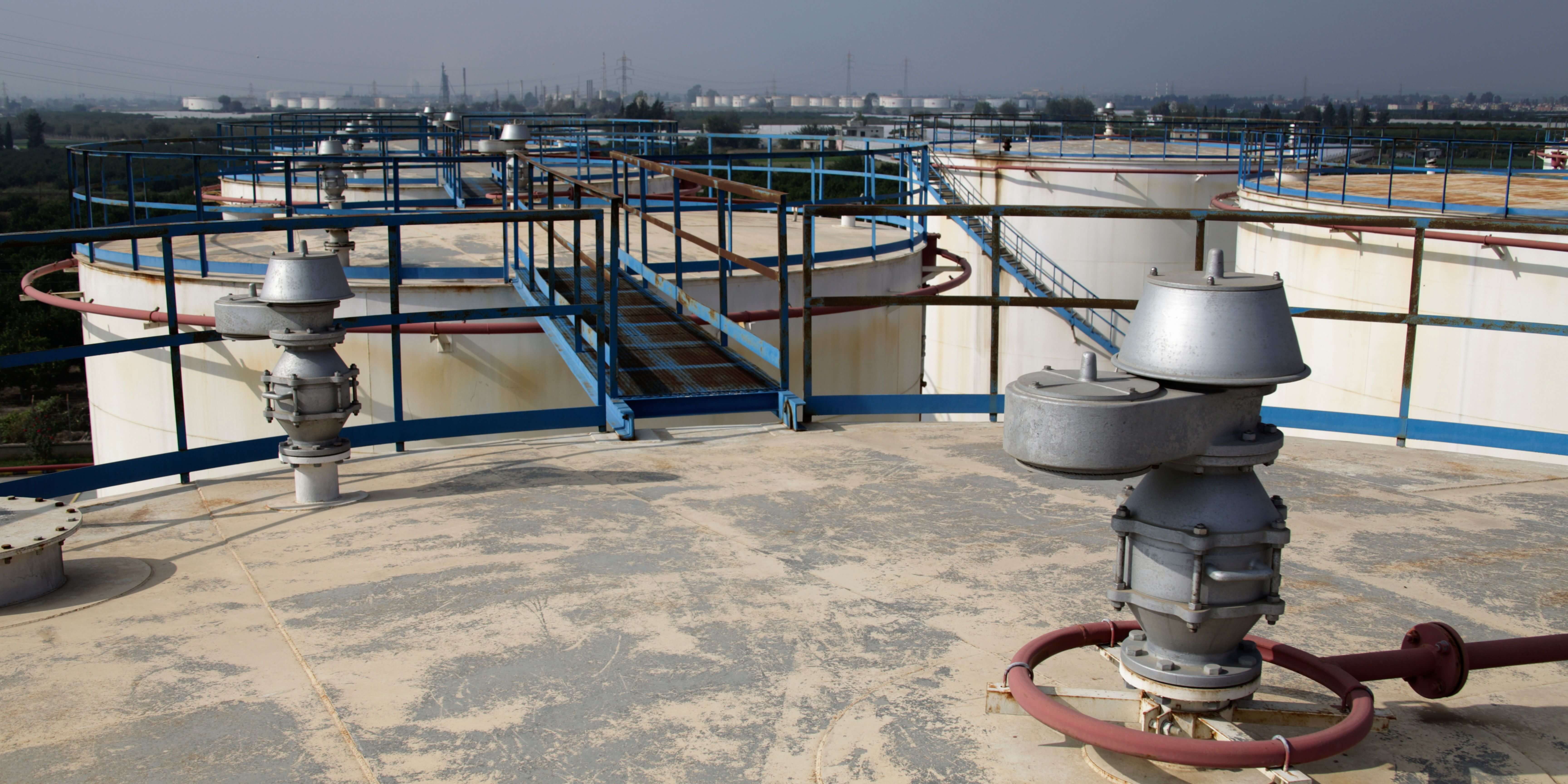
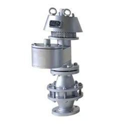
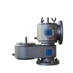
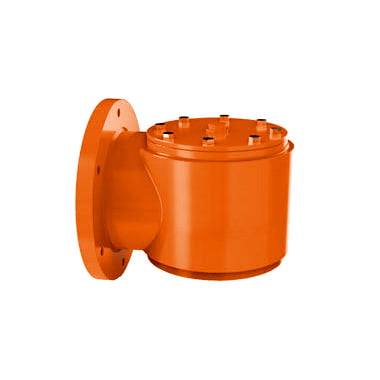
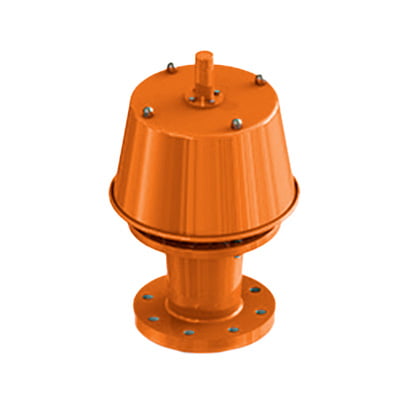
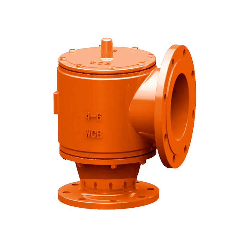
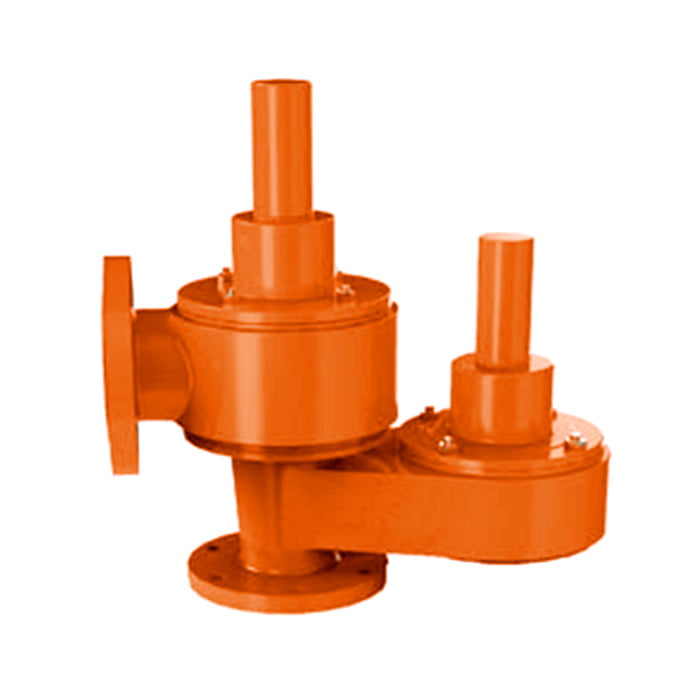
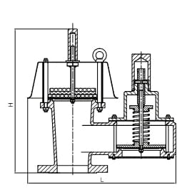
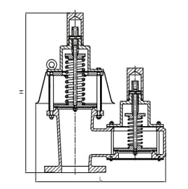
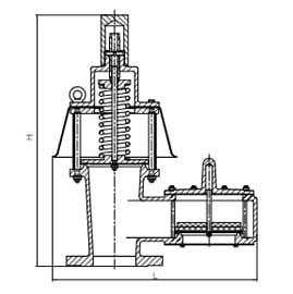
YeeValve produces Breather Valves, also known as Pressure Vacuum Relief Valves, which are full-lift valves designed for applications requiring low fugitive emissions and operation around the maximum allowable working pressure of storage tanks. These valves are engineered to activate fully and stably at just 10% overpressure.

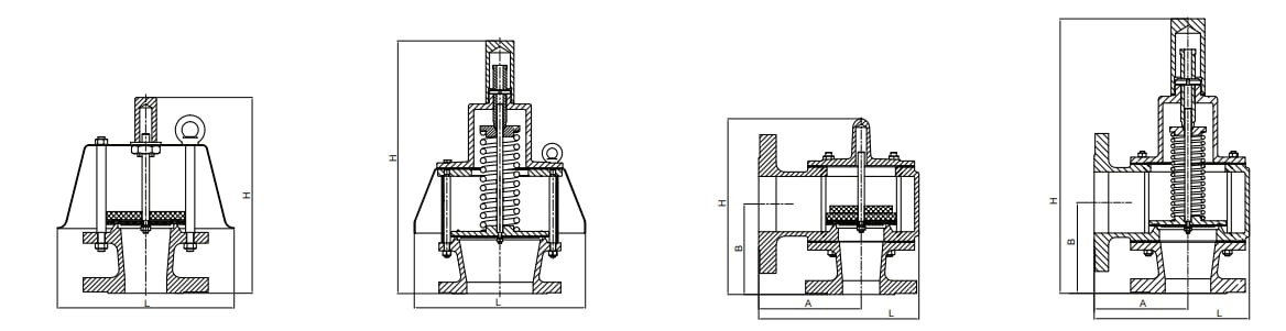
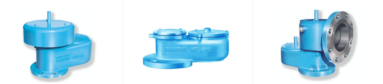
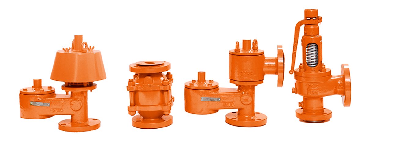
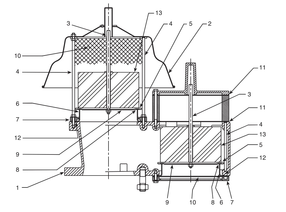
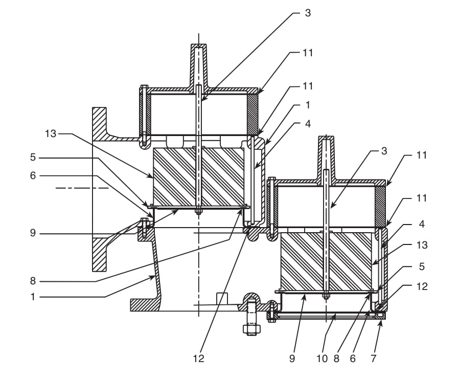
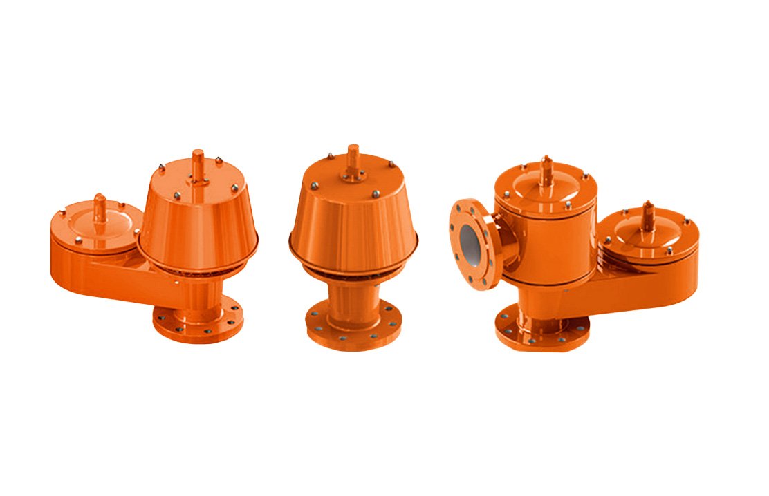
Like all YeeValve Pressure/Vacuum Relief Valves, these full-lift valves have a venting rate near zero, allowing them to reset at the preset pressure. The valves are available in various configurations, including Pressure Release, Vacuum Release, and Pressure Vacuum Release. They are also offered with different loading options such as Weight Loaded and Spring Loaded, and structural styles including Integral and Split types. This range of options ensures flexibility to meet diverse system requirements while maintaining safety and efficiency.

View Products Request A Quote
TT7120 Breather Valve

Breather Valves 101

At YeeValve, our engineers possess extensive and valuable technical experience in selecting the appropriate breather valves for storage tanks used by clients in industries such as oil and gas, refining and chemical, pharmaceuticals, and bioenergy.

Whether dealing with overpressure or vacuum conditions, such as during tank filling, emptying, steam purging, or thermal breathing, we consistently provide the best valve solutions. Atmospheric and low-pressure storage tanks are common in process industries. During operation, changes in the tank’s liquid level or external temperature can cause gas expansion or contraction, leading to pressure fluctuations. These fluctuations may result in overpressure or vacuum, potentially causing tank distortion or collapse.

To prevent these unstable conditions, our process design typically includes the installation of breathing valves on the tank top to maintain pressure balance, ensuring the tank remains undamaged during overpressure or vacuum conditions, thereby enhancing safe and effective operations, reducing volatilization and loss of materials, and promoting safety and environmental protection.

What are Breather Valves

It automatically adjusts internal and external pressures in storage tanks.

Breather valves are a crucial component of storage tanks, primarily used to prevent unstable conditions such as overpressure or vacuum within the tanks. By installing breather valves at the top of the tank, we can maintain the pressure inside the tank. This setup ensures that the tank remains undamaged in scenarios of overpressure or vacuum, thereby safeguarding the tank’s integrity. Additionally, the use of breathing valves helps minimize the loss of materials stored within the tank and reduces the volatilization of volatile organic compounds (VOCs), contributing significantly to both safety and environmental protection.

breather valve Vent-to-atmosphere parts
breather valve Pipe-away parts

Breather Valve Design and Parts

Item Material Code 1 Material Code 2
1 Body Carbon steel 316 SS
2 Weatherhood Carbon steel 316 SS
3 Guide stem 316 SS 316 SS
4 Guide posts 316 SS 316 SS
5 Pallet 316 SS 316 SS
6 Seat ring 316 SS 316 SS
7 Seat ring retainer[1] Polypropylene Polypropylene
8 Insert[1] PTFE PTFE
9 Insert retainer 316 SS 316 SS
10 Screen[1] HDPE HDPE
11 Gaskets[1] Fiber Fiber
12 O-ring[1] NBR NBR
13 Weights Lead Lead
Ask for Quote Now

Other Special Features of Our Breather Valve

Breather Valve Specifications

Different types of breather valves with different dimensions, setting pressure, and specifications. We will list all the types of pressure/vacuum relief valve data here.

Pressure & Vacuum to Atmosphere Breather Valve

TT7110, TT8110

TT7110, TT8110

Weight Loaded

TT7112, TT8112

TT7112, TT8112

Vacuum Spring Loaded

TT7113, TT8113

TT7113, TT8113

Pressure/Vacuum Spring Loaded

TT7115, TT8115

TT7115, TT8115

Pressure Spring Loaded

Nominal Diameters (Inch) Nominal Diameters (mm) L (mm) W (mm) H (mm) – TT7110, TT8110, TT7112, TT8112 H (mm) – TT7113, TT8113, TT7115, TT8115 Gross Weight (Approx. kg)
2” 50 336 215 340 530 15
3” 80 429 270 376 563 28
4” 100 487 296 435 601 55
6” 150 651 395 545 755 108
8” 200 803 496 628 859 174
10” 250 935 596 732 980 241
12” 300 1112 676 842 1130 340
Parameters Units TT7110, TT8110 TT7112, TT8112 TT7113, TT8113 TT7115, TT8115
Set Pressure – mbar (g) 2 ~ 69 2 ~ 69 69 ~ 1034 69 ~ 1034
Set Pressure – psi (g) 0.03 ~ 1.0 0.03 ~ 1.0 1.0 ~ 15.0 1.0 ~ 15.0
Set Vacuum – mbar (g) -2 ~ -43 -43 ~ -480 -43 ~ -480 -2 ~ -43
Set Vacuum – psi (g) -0.03 ~ -0.62 -0.62 ~ -6.96 -0.62 ~ -6.96 -0.03 ~ -0.62
  • Compliance with API Standard 2000: Ensures that design and testing meet industry standards.
  • Available Sizes: Ranging from 2” to 12” nominal bore to accommodate various applications.
  • Material Options: Primarily made from carbon steel and stainless steel, with alternative materials available upon request.
  • Venting: Directly vented to the atmosphere to manage internal pressure.
  • Modular Design: Facilitates easier assembly and maintenance.
  • Flange Specifications: Inlet and outlet flanges conform to ANSI 150LB RF standard, with options for other specifications.
  • FEP Diaphragms: Prevent sticking of the seat and pallet, ensuring reliable operation.
  • Customization Options: Valves can be outfitted with additional features such as a flame arrester, inlet pipe, or internal lining based on specific needs.

Pressure & Vacuum to Pipe Away Breather Valve

TT7120, TT8120

TT7120, TT8120

Weight Loaded

TT7120, TT8120

TT7122, TT8122

Vacuum Spring Loaded

TT7120, TT8120

TT7123, TT8123

Pressure/Vacuum Spring Loaded

TT7120, TT8120

TT7125, TT8125

Pressure Spring Loaded

Inlet x Outlet Size (Inch) Inlet x Outlet Size (mm) L (mm) W (mm) H (mm) – TT7120, TT8120, TT7122, TT8122 H (mm) – TT7123, TT8123, TT7125, TT8125 A (mm) B (mm) Gross Weight (Approx. kg)
2” x 3” 50 x 80 371 190 344 517 140 227 34
3” x 4” 80 x 100 461 229 404 564 156 264 58
4” x 6” 100 x 150 507 279 504 639 168 326 85
6” x 8” 150 x 200 671 343 643 829 216 414 160
8” x 10” 200 x 250 826 406 750 940 273 472 249
10” x 12” 250 x 300 955 483 881 1088 320 544 344
12” x 14” 300 x 350 1141 533 986 1237 381 619 493
Units TT7120, TT8120 TT7122, TT8122 TT7123, TT8123 TT7125, TT8125
Set Pressure – mbar (g) 2 ~ 69 2 ~ 69 69 ~ 1034 69 ~ 1034
Set Pressure – psi (g) 0.03 ~ 1.0 0.03 ~ 1.0 1.0 ~ 15.0 1.0 ~ 15.0
Set Vacuum – mbar (g) -2 ~ -43 -43 ~ -480 -43 ~ -480 -2 ~ -43
Set Vacuum – psi (g) -0.03 ~ -0.62 -0.62 ~ -6.96 -0.62 ~ -6.96 -0.03 ~ -0.62
  • Conformance to API2000: Designed and rigorously tested to meet API2000 standards.
  • Available Size Range: Offers a range from 2” to 12” nominal bore, accommodating various system requirements.
  • Material Selection:  Constructed primarily from carbon steel and stainless steel, with the option to request alternative materials as needed.
  • Venting Capabilities: Equipped with pressure vents to pipeline and vacuum vents from atmosphere; vacuum side with flanged ends can be provided upon request.
  • Modular Design: Ensures ease of assembly and maintenance flexibility.
  • Flange Compliance: Inlet and outlet flanges meet ANSI 150LB RF standards, with the ability to accommodate other specifications if required.
  • FEP Diaphragms: These components are designed to prevent the seat and pallet from sticking, enhancing operational reliability.
  • Customization Options: Valves can be custom equipped with a flame arrester, inlet pipe, or lining to meet specific operational needs.

Pressure-Only Relief Breather Valve

TT7136, TT8136

TT7136, TT8136

Vent to ATM/Weight Loaded

TT7138, TT8138

TT7138, TT8138

Vent to ATM/Spring Loaded

TT7130, TT8130

TT7130, TT8130

Pipe Away/Weight Loaded

TT7135, TT8135

TT7135, TT8135

Pipe Away/Spring Loaded

Inlet (x Outlet) Size (Inch) Inlet (x Outlet) Size (mm) L (mm) – TT7136, TT8136 L (mm) – TT7130, TT8130 H (mm) – TT7136, TT8136 H (mm) – TT7138, TT8138 H (mm) – TT7130, TT8130 H (mm) – TT7135, TT8135 A (mm) B (mm) W* (mm) – TT7136, TT8136 W* (mm) – TT7130, TT8130 Gross Weight (Approx. kg) – TT7136, TT8136 Gross Weight (Approx. kg) – TT7130, TT8130
2” (x 3”) 50 (x 80) 215 220 240 430 242 415 140 125 215 190 10 30
3” (x 4”) 80 (x 100) 270 258 267 453 291 452 156 151 270 229 17 34
4” (x 6”) 100 (x 150) 296 282 304 470 369 504 168 192 296 279 26 50
6” (x 8”) 150 (x 200) 395 368 370 580 467 653 216 238 395 343 45 90
8” (x 10”) 200 (x 250) 500 458 421 652 542 732 273 264 496 406 74 147
10” (x 12”) 250 (x 300) 600 529 495 743 643 851 320 306 596 483 106 204
12” (x 14”) 300 (x 350) 685 629 557 835 701 952 381 334 676 553 149 292
Units TT7136, TT8136 TT7138, TT8138 TT7130, TT8130 TT7135, TT8135
Set Pressure – mbar (g) 2 ~ 69 69 ~ 1034 2 ~ 69 69 ~ 1034
Set Pressure – psi (g) 0.03 ~ 1.0 1.0 ~ 15.0 0.03 ~ 1.0 1.0 ~ 15.0
  • API2000 Standard: Designed and tested in compliance with API2000.
  • Size Options: Available from 2” to 12” nominal bore, accommodating a range of system sizes.
  • Material Choices: Primarily made from carbon steel and stainless steel, with additional materials available upon request.
  • Venting Options: Can be vented to the atmosphere or connected to a pipeline.
  • Modular Design: Enhances ease of assembly and future modifications.
  • Flange Standards: Inlet and outlet flanges conform to ANSI 150LB RF, with options for other specifications available on request.
  • FEP Diaphragms: These help prevent sticking of the seat and pallet, ensuring smoother operation.
  • Customization Options: Valves can be equipped with a flame arrester, inlet pipe, or specific lining to meet unique system requirements.

Vacuum-Only Relief Breather Valve

TT7140, TT8140

TT7140, TT8140

Vertical Installation/Weight Loaded

TT7143, TT8143

TT7143, TT8143

Vertical Installation/Spring Loaded

TT8145

TT8145

Side Installation/Weight Loaded

TT8147

TT8147

Side Installation/Spring Loaded

Nominal Diameters (Inch) Nominal Diameters (mm) L (mm) – TT7140, TT8140 L (mm) – TT8145 H (mm) – TT7140, TT8140 H (mm) – TT7143, TT8143 H (mm) – TT8145 H (mm) – TT8147 A (mm) W* (mm) – TT7140, TT8140 W* (mm) – TT8145 Gross Weight (Approx. kg) – TT7140, TT8140 Gross Weight (Approx. kg) – TT8145
2” 50 307 210 383 158 18
3” 80 400 220 237 397 212 385 140 204 190 32 12
4” 100 454 258 259 394 255 415 156 228 229 46 20
6” 150 599 282 329 515 317 453 168 304 279 87 35
8” 200 729 368 385 575 400 586 216 368 343 137 68
10” 250 838 456 468 675 481 671 273 418 406 191 105
12” 300 1002 529 519 770 579 786 320 496 483 285 150
14” 350 629 634 885 381 533 210
Units TT7140, TT8140 TT7143, TT8143 TT8145 TT8147
Set Vacuum – mbar (g) -2 ~ -43 -43 ~ -480 -2 ~ -43 -43 ~ -480
Set Vacuum – psi (g) -0.03 ~ -0.62 -0.62 ~ -6.96 -0.03 ~ -0.62 -0.62 ~ -6.96

Compliance with Standards

  • Designed and tested according to API2000.

Size Variability

  • TT7140/7143, TT8140/8143 Series available from 2” to 12” nominal size.
  • TT8145/8147 Series available from 3” to 14”

Material Options

  • Primarily constructed from carbon steel and stainless steel, with other materials available upon request.

Installation Flexibility

  • Can be installed on top of the tank using a bottom flanged valve.
  • Alternatively, can be mounted on the sidewalls of the tank with side flanged valves.

Modular Design

  • Enhances adaptability and ease of maintenance.

Flange Standards

  • Inlet and outlet flanges meet ANSI 150LB RF, with the ability to accommodate other specifications as needed.

FEP Diaphragms

  • These components prevent the seat and pallet from sticking, ensuring reliable valve operation.

Customization Options

  • Valves can be equipped with additional features such as a flame arrester, inlet pipe, or specific linings tailored to meet specialized requirements.

Types of Tank Breather Valves

Tank breather valves are categorized based on their design and operational mechanisms as follows:

Design-Based Categories

Weight-Loaded Breather Valves

These valves utilize weights to regulate pressure. If the internal pressure surpasses a set limit, the force lifts the weight, triggering the valve to open. Commonly used in large storage tanks, weight-loaded valves are straightforward in operation and can be easily adjusted by modifying the weights to change pressure settings.

Weight-Loaded Breather Valves
Pilot-Operated Breather Valves

Pilot-Operated Breather Valves

Utilizing a pilot system for precise pressure management, these valves are known for their high accuracy and efficiency. They are ideal for complex systems requiring stringent control to safeguard equipment, personnel, and the environment. Pilot-operated valves provide quick response times and meticulous pressure regulation.

Spring-Loaded Breather Valves

Employing a spring mechanism to control pressure, these valves are highly resistant to fluctuations and offer finely tuned pressure adjustments. They are suitable for environments with varying pressure demands.

Spring-Loaded Breather Valves

Operation-Based Categories

Pressure-only Relief Breather Valves

Pressure-only relief breather valves are designed for applications requiring pressure relief. The vapors released by these valves can either be vented directly to the atmosphere or channeled away through piping. To prevent tank damage and ensure operational safety, these valves employ either spring or weight-loaded pallets, which can be adjusted to various set pressures according to specific needs.

Vacuum-only Relief Breather Valves

Vacuum-only relief breather valves are specifically designed for situations where vacuum relief is necessary. These valves facilitate intake relief from the atmosphere, utilizing either a spring or weight-loaded pallet to maintain the preset pressure. They can be mounted atop the tank using a bottom flanged valve or on the tank’s sidewalls with side flanged valves, depending on the installation requirements and tank configuration.

Pressure and Vacuum Relief Breather Valves to Pipe Away (Closed Line)

Pressure and vacuum relief breather valves are employed for both pressure and vacuum relief in systems where vapors need to be directed away through a closed line. These valves are equipped with special pallets featuring air-cushion sealing, which effectively minimizes air intake and vapor escape during routine operation. This design significantly reduces product loss by ensuring a tighter seal during the tank’s normal breathing cycles.

Pressure and Vacuum Relief Breather Valves to Atmosphere

Pressure and Vacuum Relief Breather Valves that vent to the atmosphere are designed to safeguard the storage tank from damage caused by over-pressure or excessive vacuum. These valves significantly reduce costly product evaporation losses that occur due to normal tank ‘breathing’.

Tank Blanketing Valves

Also known as nitrogen blanketing valves, these are crucial for the safe storage of hazardous liquids and chemicals. They introduce N2 or another inert gas into the tank, creating a protective gas layer over the liquid to shield it from atmospheric air and oxygen, thus preventing hazardous reactions. These valves are also vital for maintaining internal pressure during tank unloading or in conditions of increased vaporization due to low ambient temperatures.

Breather Valve Position

The Difference Between Breather Valve Pipe Away, Breather Valve in Pipeline and Breather Valve in Tank

What is Breather Valve Pipe Away

The term “breather valve pipe away” refers to a configuration in breather valves (also known as pressure/vacuum relief valves) where the gases and vapors released through the valve are not vented directly into the atmosphere. Instead, these emissions are directed through a piping system to a designated location.

What is Breather Valve in Pipeline

A breather valve in a pipeline system functions similarly to a breather valve on a storage tank but is adapted to the specific needs and dynamics of pipeline operations. These valves are used to manage pressure and ensure the safety and integrity of the pipeline by allowing air to enter or exit depending on the internal pressure conditions.

What is Breather Valve in Tank

A breather valve in a tank, often referred to as a pressure-vacuum relief valve, plays a crucial role in regulating the internal atmosphere of the storage tank. This valve is primarily used to manage the pressure and vacuum conditions that can arise due to changes in temperature, liquid level, or operational activities.

What is the Purpose of Breather Valve on the Tank?

Breathing valves are primarily in place to ensure that storage tanks remain safely sealed under normal conditions, minimizing the evaporation and loss of the tank’s contents. However, breather valves are activated under several abnormal conditions to manage internal pressures:

I. Material Output

When materials are being dispensed from the tank, the breather valve activates to draw air or nitrogen into the tank. This compensates for the decrease in internal volume, preventing the creation of a vacuum that could destabilize the tank.

II. Material Input

During the process of filling the tank with material, the breather valve works to expel the internal gases to the outside. This is necessary to manage the increased internal pressure caused by the addition of new contents.

III. Thermal Effects

Changes in climate or ambient temperatures can cause variations in the vapor pressure of the tank’s contents. The breather valve responds by either venting steam or drawing in air or nitrogen, commonly referred to as the response to thermal effects. This helps stabilize the internal pressure regardless of external temperature changes.

IV. Fire Incidents

In the event of a fire, the heat can cause the gases inside the tank to expand or the liquids to evaporate more rapidly. The breather valve then vents these gases to the outside to prevent the tank from experiencing overpressure, which could lead to structural failure.

V. Other Conditions

In other scenarios such as the pressurized transport of volatile liquids, chemical reactions from internal or external heat transfer devices, or operational errors, the breather valve adjusts by either venting or drawing in gases. This functionality is crucial to prevent damage from overpressure or excessive vacuum within the tank.

Breather Valves Ordering Parameter Table

Download the Sheet

Flame Arrester Ordering Parameter Table

Download the Sheet

TOP 10 Breather Valve Supplier in the World 2024

The ranking of these 10 breather valve manufacturers does not imply priority.

Varec Biogas, initially founded in the 1930s, specializes in biogas handling products with a focus on customer needs, particularly for Municipal Wastewater Treatment Plants. Acquired by Ovivo Inc. in 2019, the company remains dedicated to providing solutions for the biogas market worldwide.

Varec Biogas offers a range of products and equipment for biogas processing, including burners, flares, gas cleaning/drying systems, and gas control equipment, ensuring safe and efficient anaerobic digestion processes.

DIGESTER COVER EQUIPMENT AND ACCESSORIES

DIGESTER COVER EQUIPMENT – VALVES

  • 400W EMERGENCY PRESSURE RELIEF MANHOLE COVER

The 400W Series is designed to provide emergency pressure and/or vacuum relief in storage tanks and vessels.2010B/2020 RELIEF VALVE

The 5810B/5820B Series Relief Valve and Flame Arresters are a combination of the 2010B/2020B Series Pressure and Vacuum Relief Valve and the 5000 Series Flame Arrester.

  • 2010B/2020 RELIEF VALVE

The 2010B/2020B protects tanks from damage or deformation, and minimizes emissions to the environment, as well as loss of product due to evaporation.

  • SSV SAFETY SELECTOR

The Safety Selector Valve is designed to function as a switchover device that permits servicing of pressure relief devices with no process interruption.

  • 5000/5010 FLAME ARRESTER

The 5000/5010 Series end-of-line flame arresters are used in gas piping systems, petroleum storage tank roofs, and digester covers to prevent the propagation of aflame into the system.

  • 42 SAMPLING AND GAUGING HATCH COVER220 ROOFMANHOLE COVER

The 42 Series is designed to provide access to tanks for product gauging, temperature measurement, and sampling.

  • 220 ROOF MANHOLE COVERThe 220 Series is designed for use on tanks where quick and easy personnel access is desired.

Emerson is a renowned manufacturer that offers various types of valves, including breather valves, which are part of their broader portfolio of products for process control and automation. Emerson breather valves are designed to ensure safety, reliability, and performance in industrial applications, particularly for storage tanks in the oil and gas, chemical, and other process industries.

VAREC 2010B/2020B PRESSURE AND VACUUM RELIEF VALVES

Emerson’s weight-loaded relief valves protect tanks from damage or deformation, and minimize emissions to the environment and loss of product due to evaporation.

Applications:

  • Oil and Gas Industry: Used in oil storage tanks to manage the pressure and vacuum created by thermal changes and filling or withdrawal operations.
  • Chemical Processing: Critical in chemical tanks where vaporous emissions need to be controlled without releasing harmful substances into the environment.
  • Other Industries: Suitable for water treatment facilities, pharmaceuticals, and food processing where maintaining purity and preventing contamination are essential.

Korea Steel Power Corp. (KSPC) specializes in safety equipment for storage tanks and various industrial projects globally, ensuring total system support from planning to maintenance, emphasizing quality and customer satisfaction.


Applications

  • Storage tanks vents
  • Oil/petrochemical refineries
  • Chemical Processing plants
  • Natural gas supply Lines
  • Flare stacks
  • Vapour incineration systems
  • Vapor recovery systems
  • Sewage Treatment vapour processing
  • Pharmaceutical

Nirmal Industrial Controls Pvt Ltd, established in 1973, specializes in self-actuated pressure control valves, nitrogen blanketing systems, and gas pressure reducing stations, offering innovative solutions with a focus on quality and customer needs.

Breather Valve Specifications
  • Body Size & Ratings:

Flanged: 2″, 3″, 4″ (Higher sizes on request)

ANSI B16.5 Class 150

  • Relief Set Pressure: 20 mmWCg to 600 mmWCg
  • Set Vacuum: -20 to -600 mmWCg
  • Body: ASTM 216 Gr. WCB (Std), A351 Gr. CF8, A351 Gr. CF8M, A351 Gr. CF3, A351 Gr. CF3M
  • Internal Trim Parts*: A479 Gr. SS316 (Std)

* NACE & other special material available on request.

  • Disc: Nitrile (Standard), Neoprene, EPDM, Viton, PTFE, FEP
  • ‘O’ Rings: Nitrile (Standard), Neoprene, EPDM, Viton, PTFE, FEP
  • TEMPERATURE CAPABILITIES: – 45 C to 200 C with different elastomeric parts.

GROTH Corporation, LLC. originated in the 1960s as a valve company in Houston, Texas, and has evolved into a global leader providing pressure relief products worldwide, emphasizing quality, customer service, and commitment to safety.

Groth Corporation is a well-regarded manufacturer known for producing high-quality pressure relief valves, including breather valves. Groth breather valves are designed to manage pressure and vacuum conditions in storage tanks, preventing damage from overpressure or vacuum conditions that could arise from thermal changes, liquid movement, or other operational factors.

The main Relief Valves of Groth

  • Pressure/Vacuum Relief Valve Vent to Atmosphere
  • Pressure/Vacuum Relief Valve with Pipe-Away
  • Spring Loaded Pressure/Vacuum Relief Valve – Vent to Atmosphere
  • Spring Loaded Pressure/Vacuum Relief Valve
  • Pressure/Vacuum Relief Valve
  • Weight Loaded Pressure Relief Valve
  • Weight Loaded Pressure/Vacuum Relief Valve
  • Pressure/Vacuum Relief Valve with Pressure Spring
  • Pressure/Vacuum Relief Valve with Vacuum Spring
  • Pressure/Vacuum Relief Valve with Pressure & Vacuum Springs
  • Pressure/Vacuum Relief Valve with Pipe-away Feature and same-size inlet and outlet

Costruzioni Meccaniche Lupi S.r.l., a precision mechanical company founded in the 1950s, specializes in manufacturing safety equipment for storage tanks. They have a state-of-the-art blow testing plant, hold ISO 9001 certification, produce high-quality valves and flame arresters, achieved energy self-sufficiency with a solar plant in 2010, utilize CNC machines for production, provide venting requirement calculations, and export over 50% of their sales globally.

LUPI Breather Valve Advantages and Features

Compliance with International Standards
  • LUPI Breather Valves, also known as Pressure-Vacuum Relief Valves, are meticulously designed according to ISO 28300 and API 2000 standards. This ensures that they meet the rigorous requirements for safe filling, emptying, and operation of low-pressure storage tanks.
Expert Valve Sizing and Customization
  • LUPI’s technical department specializes in valve sizing according to “API 2000” and “ISO 28300,” ensuring that each valve is optimized for specific operational needs.
  • Custom configurations are available to meet European Standards associated with the “Atex” directive, including EN1127-1 for explosion prevention and ISO 80079-36 and 80079-37 for non-electrical equipment in explosive atmospheres.

Rampini S.r.l., founded in Milan in 1950, has a long history of specializing in tank fittings. The company’s expertise focuses on pressure and vacuum relief devices, emergency vents, and gauge board level indicators, which are now utilized in numerous refineries and petrochemical and pharmaceutical plants worldwide.

PROTEGO® is a well-known brand that specializes in safety and environmental protection technologies for the process industry, particularly known for its breather valves. PROTEGO® breather valves are designed to protect atmospheric and pressurized storage tanks from excessive pressure and vacuum. These devices are used widely across various industries, including oil and gas, chemicals, and pharmaceuticals, ensuring safe storage and handling of volatile liquids and gases.

A Legacy of Family Leadership:

  • Robert Leinemann (1954 – 1967): Founded the company, setting the foundation with strong values and innovative visions.
  • Hubert Leinemann (1967 – 2000): Carried on his father’s legacy, overseeing significant growth and technological advancements.
  • Christoph Leinemann (1992 – 2013): Continued to expand the company’s reach and technological footprint, enhancing its global impact.

Today PROTEGO maintains its commitment to product innovation and quality, providing reliable research capabilities, engineering expertise and high-quality breathing valves to customers in the oil and gas upstream and downstream industries, as well as the petroleum, chemical, pharmaceutical and bioenergy industries.

Since 1925 Protectoseal has been an industry pioneer and leading manufacturer of quality products that conserve and control volatile emissions and protect low pressure storage tank, vessels and process from fire and explosion.

Protectoseal offers a comprehensive range of pressure and vacuum relief vents, flame arresters, and vapor control devices. These products are commonly utilized in various industries such as Chemical and Petrochemical, Oil, Gas and Petroleum, Bulk Storage, Alternative Fuels, Pharmaceuticals, Food/Beverage, Semiconductor, and Pulp and Paper.

YeeValve is an expert supplier of storage tanks and process safety equipment. It is affiliated with THINKTANK Corporation. In 2019, Co-Founder Will Don separated the storage tank system business under the original STONE (Taiwan) and THINKTANK. It aims to provide more professional, fast service for our Tank Systems Engineering customers. Will Don has 16 years of industry experience and is a professional in the process control industry. YeeValve’s technical team is composed of 7 professional technical engineers on storage tanks. The entire foreign trade business team has received professional technical training, aiming to quickly respond to customers’ business inquiries and provide professional technical support. YeeValve has a standard operating process from quotation, selection, drawings, and technical services.

As experts in tank storage and process safety, YeeValve’s products have obtained ISO9001:2015, ISO14001:2015, PED, ATEX, UL, FM, CE, and other certificates. We provide a range of engineered products and services for the fluid processing, transmission, and storage industries. This includes professional product sales, consulting, on-site maintenance, and custom installation. YeeValve’s products are used in a wide range of applications, including power plants, chemicals, food and beverage, pharmaceuticals, petrochemicals, biofuels/anaerobic digestion, aerospace, and utilities. We are proud to provide safety equipment for the flammable and non-flammable storage tanks, which meet strict international standards, demonstrating our commitment to safety, environmental responsibility, and cost-effectiveness.

Pressure Testing and Inspection Procedures for Breather Valves

The comprehensive testing and inspection procedures can ensure that the breather valves operate reliably under various conditions, confirming their effectiveness and safety in real-world applications.

1. Test Preparation

  • Installation: Ensure the flame arrestor breather valve is correctly mounted on the test bench. The setup should be leak-free, and the interior walls of the test tubing must be smooth and even.

2. Testing Medium

  • Air Testing: The medium for testing the opening pressure, ventilation capacity, and leakage of the flame arrestor breather valve is air. The specifications are absolute pressure at 0.1 Mpa, temperature at 20°C, relative humidity at 50%, and density at 1.2 kg/m3. Adjust calculations accordingly if the air conditions differ.
  • Water Testing: The medium for testing valve body pressure is clean water at temperatures ranging from 5 to 35°C.

3. Air Pressure Testing

  • First, measure the leakage volume of the breather valve
  • Second, proceed to test each unit for sensitivity and airflow capacity.

4. Water Pressure Testing

  • Conduct a water pressure test on the breather valve with flame arrestor at 0.2 Mpa, maintaining this pressure for 10 minutes.

5. Pressure Testing

  • Mount the valve on the air storage tank’s connecting flange.
  • Adjust the valve to gradually increase or decrease the pressure inside the tank.
  • Set the valve disc to an open position and record the pressure readings from the connected manometer every minute.
  • Rotate the valve disc by 90° and 180° and repeat the test for each position, conducting three trials per condition and averaging the results.

6. Leakage Testing

  • Test for leakage at 0.75 times the operating pressure, taking readings from the manometer.
  • Record the leakage values from the flow meter (accuracy between 0.5-1.0) every minute for three minutes and average these values.

7. Low-Temperature Testing

  • Install the flame arrestor breather valve on a test rig inside a low-temperature chamber.
  • Lower the temperature within the chamber to between 4-15°C while continuously introducing ambient air at a relative temperature of no less than 70%.
  • Before the valve disc opens, allow the breather valve to acclimatize within the chamber, then reduce the temperature to -30°C and maintain for 24 hours.
  • Connect one side of the test rig to a manometer and the other side to an air supply tank with ambient air.
  • Record the pressure readings when the valve disc is in the open position. Repeat this three times.

Breather Valve Installation Guide

Breather valves play a crucial role in maintaining pressure balance within storage tanks, reducing media evaporation, and safely harnessing the tank’s capacity to minimize emissions. So we need to carefully follow the installation guide step by step.

Step 1. Unpack the Valve

Begin by carefully removing the valve from its packaging. It is vital to read the product instructions thoroughly to understand specific handling and installation details.

Step 2. Handling the Valve

Use appropriate lifting tools to handle the breather valve. This prevents damage to the valve disc and protective cap.

Step 3. Prepare the Mounting Surface

Inspect the coaxiality and perpendicularity of the flange on the tank or reservoir. Proper alignment of these elements is crucial for the normal operation of the pressure vacuum relief valve (breather valve).

Step 4. Inspect the Flange Surface

Check the flange surface on the tank or reservoir. It should be clean, free from scratches, corrosion, tool marks, and must be flat to ensure a secure seal.

Step 5. Remove Protective Covers

Take off any flange connection port protective caps and additional packing materials.

Step 6. Check the Gasket

Examine the gasket to ensure it is suitable for use. The gasket material should be compatible with the tank contents and operational conditions.

Step 7. Position the Gasket and Bolts

Center the gasket on the flange and secure it using bolts. Ensure that the bolts are evenly tightened to distribute pressure uniformly, which helps prevent leaks and ensures the valve functions correctly.

Meanwhile, based on the different conditions and tanks, we also need to pay attention to the specific guidelines for installation of breather valves, to ensure the tank system’s optimal functionality and safety:

I. Topmost Installation

Breather valves should be installed at the highest point on the top of the tank. Theoretically, to minimize evaporation losses and facilitate efficient venting, the valve should be positioned at the highest point of the tank’s gas space, providing the most direct and largest passage to the breather valve.

II. Dual Valve Installation for Large or Critical Tanks

For large tanks or tanks of critical importance, it is advisable to install two breather valves to mitigate the risk of overpressure or vacuum due to a single valve failure. To prevent both valves from operating simultaneously and increasing the likelihood of failure, they are typically designed with staggered pressure thresholds in the process design, allowing one to operate normally while the other serves as a backup.

III. Multiple Valves for High Venting Requirements

If the venting requirements exceed the capacity of a single breather valve, installing more than two valves may be necessary. When two breather valves are installed, they should be symmetrically placed at equal distances from the center of the tank top to ensure balanced operation.

IV. Installation on Nitrogen-Blanketed Tanks

When installing a breather valve on a nitrogen-blanketed tank, the nitrogen supply pipe should be positioned well away from the breather valve interface and inserted about 200mm into the tank from the top. This setup prevents the nitrogen from being directly vented out upon entry, maintaining the nitrogen blanket effectively.

V. Consideration for Flame Arresters

If a breather valve includes a flame arrester, the pressure drop across the arrester must be considered to ensure it does not affect the valve’s ability to relieve pressure, which could otherwise lead to overpressurization of the tank.

VI. Frost Protection in Cold Climates

In regions where the average temperature of the coldest month is at or below 0°C, breather valves must have frost protection measures to prevent the valve discs from freezing or becoming blocked. This ensures that the tank can vent and intake air properly, avoiding potential overpressure bulging or vacuum collapse of the tank.

These installation requirements are designed to optimize the performance and safety of storage tanks under varying conditions, ensuring that the tanks operate efficiently while preventing any safety hazards.

Breather Valve Maintenance

Breather valves should be maintained and inspected once a month, and twice a month during the winter season. The maintenance procedure is as follows:

Step 1. Accessing the Valve

Begin by gently opening the valve cover to access the internal components.

Step 2. Inspection and Cleaning

  • Remove the vacuum and pressure discs from the valve.
  • Inspect the valve discs and their seals, as well as the guide rods and their sleeves, for any oil residue or debris.
  • Clean any contaminants found thoroughly to ensure smooth operation.

Step 3. Reassembly and Testing

  • Reinstall the discs and move them up and down several times to check for smooth and reliable operation.
  • If the movement is unhindered and everything functions as expected, secure the valve cover tightly.

Step 4. Monitoring and Immediate Action

  • During maintenance, if you notice any scratches, wear, or other abnormal signs on the valve discs, replace them immediately or contact the supplier to resolve the issue promptly.

So we recommend the engineers on site should regularly maintain and inspect breather valves, not only to ensure proper functioning but also extending their operational life and prevents potential failures, thereby safeguarding the storage tanks.

Acceptance Standards for Breather Valves

To ensure the reliability and safety of breather valves, which are critical components in maintaining the operational integrity of storage tanks, a strict set of acceptance standards must be followed. These standards include several key aspects, from visual inspections to functional testing. Here are the detailed standards compiled by YeeValve regarding the criteria breather valves must meet before they can be used.

1. Visual Inspection

  • General Appearance: The valve must be free from any physical damage such as dents, scratches, or corrosion.
  • Component Integrity: All parts, including the valve body, discs, and seals, should be intact and show no signs of improper installation or manufacturing defects.

2. Dimensional Accuracy

  • Ensure all dimensions of the breather valve conform to the specifications outlined in the technical drawings and documentation.
  • Verify that the fitment details like flange size, bolt circle diameter, and gasket grooves are accurate to ensure a perfect seal when installed.

3. Material Verification

  • Conduct material tests to confirm that the valve body materials correspond to the specifications required for the intended service environment. This may include checking for material grade and chemical composition.

4. Operational Testing

  • Pressure and Vacuum Release: Test the valve under simulated operating conditions to ensure it opens and closes at the designated pressure and vacuum settings.
  • Leak Test: Perform leak testing to ensure that there are no uncontrolled escapes of air or fluid under normal operating conditions.
  • Flow Capacity: Verify that the breather valve meets the required flow capacity to handle expected pressures and volumes efficiently.

5. Durability and Performance Tests (Option)

  • Subject the valves to a series of durability tests to assess their performance over time and under various environmental conditions. This includes cycle testing the mechanism to ensure longevity and reliability.

6. Compliance with Standards

  • Confirm that the breather valve meets or exceeds industry standards such as API 2000:2014, EN ISO 28300:2016, SY/T 0511.1-2010 GB5908-2005, or any other relevant standards governing storage tank safety and emissions control.

7. Documentation and Certification

  • Ensure that each valve comes with complete documentation, including quality assurance certificates, material test reports, and operational manuals.
  • Certificates of compliance with applicable standards and regulations should be provided, such like PED, and ATEX certificates.

WHY EMISSIONS FROM STORAGE TANK

From the storage of organic liquids occur because of evaporative loss of the liquid during its storage and as a result of changes in the liquid level.

What is Breathing Losses

Breahting losses refer to the evaporation losses from a storage tank that occur under static conditions—that is when there is no filling, emptying, or other disturbances in the tank. These losses are primarily driven by the natural breathing of the tank due to temperature and pressure variations over time, also known as standing losses.

What is Working Losses

Working emissions refer to losses that occur due to human-operated loading and unloading activities. During loading, if the tank’s internal pressure exceeds the release pressure, vapors are expelled from the tank. Unloading losses occur when the liquid level decreases, the air is drawn into the tank, and this air becomes saturated with organic vapors, expanding beyond the capacity of the vapor space.

Breathing Losses Calculation

The respiratory emissions from fixed-roof tanks can be estimated using the following formula:

LB=0.191×M(P/(100910-P))^0.68×D^1.73×H^0.51×△T^0.45×FP×C×KC

  • LB is respiratory discharge volume of fixed top tank (kg/a).
  • M is the molecular weight of the vapors in the tank.
  • P is the actual vapor pressure under bulk liquid conditions (Pa).
  • D is the diameter of the tank (meters).
  • H is the average vapor space height (meters).
  • ΔT is the average daily temperature difference (°C).
  • FP is the coating factor (dimensionless), which varies between 1 and 1.5 depending on the condition of the paint.
  • C is the adjustment factor for tanks with small diameters (dimensionless); for tanks with a diameter between 0 to 9 meters, C=1-0.0123(D-9)^2; For tanks with a diameter greater than 9 meters, C=1.
  • KC is the product factor (0.65 for crude oil, 1.0 for other organic liquids).

How Does Breather Valve Work

Breather valve combines a pressure valve and a vacuum valve, and it is mounted on atmospheric or low-pressure storage tanks. It operates automatically in response to changes in internal positive and negative pressures, maintaining the differential pressure within allowable limits. This system sustains the pressure balance within the tank, utilizing the tank’s inherent pressure capacity to minimize emissions. The operation of the tank’s exhaust positive pressure and intake negative pressure is controlled by the weight of the pressure and vacuum discs.

When the pressure of the medium in the tank is within the control operating pressure range of the breathing valve, the breathing valve does not work to maintain the tightness of the oil tank.

When the medium is added to the tank to increase the pressure in the upper gas space in the tank and reaches the operating positive pressure of the breather valve, then the pressure relief valve is lifted, which means breather valve is opened and allows the gas to escape through the outlet port of the breather valve, so that the pressure in the tank no longer continues to increase.

Conversely, when the medium is extracted from the tank, it makes the pressure in the upper gas space drop to the operating negative pressure, and the atmospheric air pushes open the vacuum disc of the breather valve, allowing external air to enter and stabilize the internal pressure, so that it can maintain equilibrium with the external atmosphere and protect the tank.

Get an instant quote

Why Buy Breather Valves from YeeValve?

Features and Benefits of Purchasing Breather Valves from YeeValve

1. High Flow Capacity

Our Pressure/Vacuum Relief Valves offer high flow rates from a compact design, maximizing efficiency.

2. Versatile Settings

A broad range of pressure and vacuum settings ensures optimal tank protection while minimizing gas losses.

3. Industry Compliance

YeeValve’s breather valves are designed and manufactured to meet API Standard 2000:2014 and EN ISO 28300:2016, which ensures high-quality and reliability for the end-users.

4. Enhanced Sealing

Our valves with superior sealing technology meet the strict requirements of emission control regulations.

5. Exceptional Leakage Control

YeeValve exceed the seat leakage standards set by API Std 2000:2014 and EN ISO 28300:2016, with no measurable leakage below 90% of set pressures and less than 1 SCFH (0.03 m3/h) at 90% of the set pressure.

6. Reduced Evaporation Loss

Our breather valve with Low leakage rates significantly cut down on evaporation losses, preserving more of your product.

7. Cost Savings

With economic benefits arise from minimized product loss from YeeValve breather valves, which enhances overall operational efficiency.

8. Customization Options

We do not only produce standard valves but also provide custom services, such as different connection requests from engineering companies to meet their specific installation needs.

9. Valve Sizing Service

We provide a valve sizing service to ensure optimum valve performance and a cost-effective technical specification to meet our customers’ unique needs.

10. YeeValve Technical Support

YeeValve offers professional technical support to assist with any inquiries or issues, ensuring smooth operation and maintenance.

Industrial Breather Valve Applications

  • Oil Storage Tanks: Breather valves are used to manage the pressure and vacuum created due to changes in temperature, filling, or emptying, helping to prevent tank overpressure or vacuum collapse.
  • Chemical Storage Tanks: In the chemical industry, these valves protect tanks from implosion or explosion by balancing internal and external pressures, especially important for volatile chemicals.
  • Pharmaceutical and Biotech Facilities: They maintain sterile conditions in storage systems by preventing contamination while controlling pressure levels, critical for sensitive materials.
  • Fuel Tanks: Used in fuel storage systems to prevent the build-up of excessive pressure or vacuum which can lead to tank failure or fuel evaporation.
reviews

What Our Clients Say

Find the engineering companies like you, how they feel THINKTANK, and YeeValve benefit their business.

More Questions?

    Breather Valve Questions | FAQs

    1. What is a Breather Valve for a Vessel

    A breather valve for a vessel is a device installed on storage tanks or vessels to prevent overpressure or vacuum conditions by allowing the tank to breathe in or exhale air. This helps maintain the pressure within safe operating limits, preventing potential damage or collapse of the vessel.

    2. Why is the Breather Valve Used in a Storage Tank

    Breather valves, or pressure/vacuum relief valves, are essential for maintaining safe operational pressures in storage tanks. They prevent structural damage by allowing tanks to vent excess pressure or intake air to mitigate vacuum conditions. This functionality ensures compliance with safety and environmental standards, optimizing the operational efficacy and longevity of the storage system.

    3. Does a Fuel Tank Need a Breather Valve

    Yes, a fuel tank needs a breather valve. This valve is crucial for allowing air to enter the tank as fuel is drawn out, preventing a vacuum that could impede fuel flow or damage the tank. Additionally, it allows the tank to vent excess pressure caused by the expansion of fuel due to temperature changes. Ensuring proper air balance within the tank, a breather valve helps maintain optimal performance and safety of the fuel storage system.

    4. What is the Breather Valve on a Tanker Ship

    The breather valve on a tanker ship is to prevent overpressure and vacuum conditions that could damage the tank, ensuring safe and compliant operations, it’s very important to main the pressure for the cargo oil tanks.

    5. What is the Use of Fuel Tank Breather Valve

    The fuel tank breather valve is used to ensure that the air pressure inside the fuel tank is balanced with the outside atmosphere.

    Here are the primary functions of a fuel tank breather valve:

    • Pressure Regulation: It prevents excessive pressure build-up in the fuel tank caused by the expansion of fuel due to temperature increases. If this pressure isn’t relieved, it could lead to tank expansion or rupture.
    • Vacuum Prevention: It allows air to enter the tank as fuel is consumed, preventing a vacuum that could potentially collapse the tank or disrupt fuel flow to the engine.
    • Reduces Emissions: The valve helps to manage the emissions from the fuel tank by allowing the tank to breathe through a charcoal canister, which absorbs vapors before they are released into the atmosphere, thereby reducing pollution.
    • Safety: It ensures the safety of the vehicle by maintaining proper pressure levels, reducing the risk of fuel vapor ignitions outside the tank.

    6. What is the Difference Between Flame Arrestor and Breather Valve

    Flame arrestors and breather valves are both important safety devices in industrial and vehicle systems, but they serve different functions:

    Flame Arrestors:
    • Purpose: Flame arrestors are designed to stop the propagation of flames. They are used in systems where there is a risk of explosion or fire due to the ignition of flammable gases or vapors.
    • Function: They work by cooling the flame as it attempts to pass through channels or metal elements within the arrestor, extinguishing it before it can ignite a larger volume of flammable material.
    • Applications: Commonly found in fuel storage tanks, gas pipelines, and exhaust systems where they prevent flames from traveling back into a system that could cause an explosion.
    Breather Valves:
    • Purpose: Breather valves, or pressure/vacuum relief valves, regulate the pressure within tanks and vessels to prevent structural damage due to overpressure or vacuum conditions.
    • Function: These valves automatically open at preset pressure or vacuum levels to allow gases to vent out or air to enter, thus stabilizing the internal pressure.
    • Applications: Used in chemical tanks, fuel storage tanks, and other vessels where pressure equalization is necessary to prevent tank rupture or implosion.

    7. What is the Difference Between Breather Valve and PVRV

    The terms “breather valve” and “PVRV” (Pressure/Vacuum Relief Valve) essentially refer to the same type of device.

    Breather Valve:
    • A breather valve typically refers to a type of valve used to manage pressure differentials in enclosed spaces, such as fuel tanks or storage containers. It allows the tank to “breathe,” letting air in and out as necessary to equalize pressure due to changes in temperature or volume of the contents.
    PVRV (Pressure/Vacuum Relief Valve):
    • PVRV is a more specific term that explicitly indicates the dual function of the device: managing both overpressure and vacuum conditions within tanks and vessels. It protects against the risks of tank rupture due to overpressure or collapse due to vacuum conditions that could occur during normal operations, such as filling, emptying, or thermal changes.

    In many cases, these terms are used interchangeably since both types of valves perform the same essential functions of balancing internal and external pressures to protect the integrity of the storage system and ensure safety. The choice of term can depend on industry-specific language or even regional preferences.

    8. What are the Requirements for a Breather Valve?

    The requirements for a breather valve are designed to ensure it functions effectively to protect tanks and vessels from overpressure and vacuum conditions. These requirements are typically guided by safety standards, operational efficiency, and industry-specific regulations. Here are the key requirements:

    1. Performance Specifications:
      • Pressure and Vacuum Settings: The valve must have specific settings for opening at designated pressure and vacuum levels, tailored to the operational and safety needs of the system.
      • Flow Capacity: It should have sufficient flow capacity to relieve pressure or admit air quickly enough to prevent damage under rapidly changing conditions.
    2. Material Compatibility:
      • Corrosion Resistance: Materials used in the construction of breather valves must be compatible with the substances stored in the tank to resist corrosion or degradation.
      • Temperature Tolerance: Materials should also withstand the temperature extremes of the environment and the contents of the tank.
    3. Safety and Compliance:
      • Certifications: Breather valves should meet relevant industry standards and certifications, such as API 2000, ISO 28300, and local safety regulations.
      • Leak Tightness: A high level of seal integrity is necessary to minimize vapor emissions and prevent air ingress when the valve is closed.
    4. Operational Durability:
      • Maintenance and Testing: Valves must be designed for easy maintenance and testing to ensure long-term reliability.
      • Robustness: They should be robust enough to handle the mechanical and operational stresses, including repeated opening and closing cycles.
    5. Environmental Considerations:
      • Emission Control: Valves often need to be equipped with features that limit environmental emissions to comply with environmental protection standards.
      • Noise Control: Especially in residential or sensitive areas, the noise generated by the venting process should be minimized.
    6. Installation Requirements:
      • Mounting: Proper mounting on the tank or vessel is crucial, usually at the highest point to effectively release gases or admit air.
      • Accessibility: Placement should allow for easy access for inspection, maintenance, and replacement.

    These requirements ensure that the breather valve performs reliably under varying conditions, providing essential protection for the storage system and compliance with safety and environmental regulations.

    9. What is the Pressure Setting for a Breather Valve

    The pressure setting for a breather valve, which controls when the valve opens to relieve excess pressure or allows air in to prevent vacuum conditions, varies based on the specific requirements of the system or tank it is protecting. The settings are critical for ensuring the safe operation of storage tanks containing liquids or gases and depend on factors such as:

    1. Type of Content: Different materials may expand or contract at different rates or may be more susceptible to certain pressures, influencing the pressure settings.
    2. Tank Design: The construction and design of the tank, including its material and thickness, determine the maximum allowable pressure and vacuum.
    3. Operational Conditions: Conditions under which the tank operates, including environmental factors like temperature and altitude, can affect the required settings.

    Typically, pressure settings for breather valves are as follows:

    • Pressure Relief Setting: Usually set just above the normal operating pressure to prevent frequent opening. Common settings might range from a few inches of water column (e.g., 2 to 6 inches WC) for atmospheric tanks up to several pounds per square inch (psi) for pressurized systems.
    • Vacuum Relief Setting: Generally set slightly below atmospheric pressure to ensure the tank does not undergo negative pressure. Typical settings are also in the range of a few inches of water column below atmospheric pressure.

    For instance, in petroleum storage tanks according to API Standard 2000, the recommended pressure settings for a breather valve are typically around 3.5 kPa (0.5 psi) for pressure relief and -2.5 kPa (-0.36 psi) for vacuum relief, but these can vary based on specific engineering requirements and safety standards.

    For the most accurate and safe settings, it’s essential to refer to the manufacturer’s specifications, comply with relevant industry standards, and consider any regulatory requirements applicable to the specific installation. Also welcome you to ask for a free consultation from the YeeValve team.